


26
Options Guide
RX220
Installing a second processor
Processors
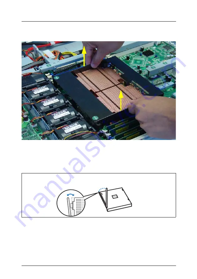
Removing the ventilation duct
Figure 6: Removal of the ventilation duct
Ê
Lift off the ventilation duct upwards.
Installing the processor
Figure 7: Opening the socket lever
Ê
Release the socket lever by pressing it sideways and lifting it up as far as it
will go.