MB95630H Series
470
FUJITSU SEMICONDUCTOR LIMITED
MN702-00009-1v0-E
CHAPTER 22 UART/SIO
22.6 Operations and Setting Procedure Example
22.6.2
Operations in Operation Mode 1
Operation mode 1 operates in clock synchronous mode (SIO).
■
Operations in UART/SIO Operation Mode 1
Setting the MD bit in the UART/SIO serial mode control register 1 (SMC1n) to "1" selects
synchronous clock mode (SIO).
The character bit length in synchronous clock mode (SIO) is variable between 5 bits and 8 bits.
Note, however, that parity is disabled and no stop bit is used.
The serial clock is selected by the CKS bit in the SMC1n register. Select the dedicated baud
rate generator or external clock. The SIO performs shift operation using the selected serial
clock as a shift clock.
To input the external clock signal, set the SCKE bit to "0".
To output the dedicated baud rate generator output as a shift clock signal, set the SCKE bit to
"1". The serial clock signal is obtained by dividing clock by two, which is supplied by the
dedicated baud rate generator. The baud rate in the SIO mode can be set in the following range.
(For more information about the dedicated baud rate generator, also see "CHAPTER 23
UART/SIO DEDICATED BAUD RATE GENERATOR".)
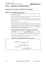
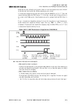
The baud rate applied when the external clock or dedicated baud rate generator is used is
obtained from the corresponding equation illustrated below.
Figure 22.6-9 Calculating Baud Rate Based on External Clock
Table 22.6-4 Baud Rate Setting Range in Clock Synchronous Mode (SIO)
PSS[1:0]
BRS[7:0]
0b00 to 0b11
0x01(1) to 0xFF(255), 0x00(256)
(The highest and lowest baud rate settings are 0x01 and 0x00, respectively.)
Baud rate value =
1
[bps]
External clock
*
*
: External clock
More than 4 machine clock
More than 4 machine clock

