MB95630H Series
314
FUJITSU SEMICONDUCTOR LIMITED
MN702-00009-1v0-E
CHAPTER 18 8/16-BIT PPG
18.6 Operations and Setting Procedure Example
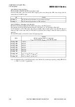
Figure 18.6-2 Operation of 8-bit PPG Independent Mode
Example for setting the duty to 50%
When PDS is set to "0x02" with PPS set to "0x04", the PPG output is set at a duty ratio of
50% (PPS setting value /2 set to PDS).
5
4
3
2
1
5
4
3
2
1
5
4
3
2
S
ynchronizing with m
a
chine clock
(1)
(2)
α
Downco
u
nter v
a
l
u
e m
a
tche
s
m
a
tche
s
d
u
ty
s
etting v
a
l
u
e
(Norm
a
l pol
a
rity)
PPGn0 Pin
(Inver
s
ion pol
a
rity)
Co
u
nter
b
orrow
PPG o
u
tp
u
t
s
o
u
rce
m=5
n=4
S
top
(1) = n
×
T
(2) = m
×
T
T: Co
u
nt clock cycle
m: PP
S
regi
s
ter v
a
l
u
e
n: PD
S
regi
s
ter v
a
l
u
e
α
: The v
a
l
u
e ch
a
nge
s
depending
on the co
u
nt clock
s
elected
a
nd
the
s
t
a
rt timing.
Co
u
nt clock
(Cycle T)
PEN
(Co
u
nter
s
t
a
rt)
PPG timer n0 co
u
nter v
a
l
u
e
D
u
ty
s
etting
(PD
S
)
Cycle
s
etting
(PP
S
)
S
top

