MB95630H Series
MN702-00009-1v0-E
FUJITSU SEMICONDUCTOR LIMITED
107
CHAPTER 8 HARDWARE/SOFTWARE WATCHDOG TIMER
8.4 Register
8.4.1
Watchdog Timer Control Register (WDTC)
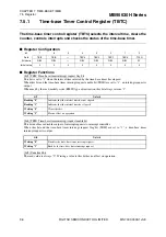
The watchdog timer control register (WDTC) activates or clears the watchdog
timer.
■
Register Configuration
■
Register Functions
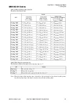
[bit7:6] CS[1:0]: Count clock switch bits
[bit5] CSP: Count clock select sub-CR selector bit
These bits select the count clock of the watchdog timer.
Write to these bits at the same time as activating the watchdog timer by the watchdog control bits.
No change can be made once the watchdog timer is activated.
Note: Since the time-base timer is stopped in subclock mode or sub-CR clock mode, always select the output
of the watch prescaler in subclock mode.
[bit4] HWWDT: Hardware watchdog timer start bit
This is a read-only bit used to confirm the start/stop of the hardware watchdog timer.
bit
7
6
5
4
3
2
1
0
Field
CS1
CS0
CSP
HWWDT
WTE3
WTE2
WTE1
WTE0
Attribute and initial values for software watchdog timer
Attribute
R/W
R/W
R/W
R
W
W
W
W
Initial value
0
0
0
0
0
0
0
0
Attribute and initial values for hardware watchdog timer
Attribute
R
R
R
R
W
W
W
W
Initial value
0
0
1
1
0
0
0
0
bit7
bit6
bit5
Details
(F
CH
: main clock, F
CRH
: main CR clock, F
MCRPLL
: main CR PLL clock,
F
CL
: subclock, F
CRL
: sub-CR clock)
Writing
0
0
0
Output cycle of time-base timer (2
21
/F
CH
, 2
20
/F
CRH
or 2
20
/F
MCRPLL
)
Writing
0
1
0
Output cycle of time-base timer (2
20
/F
CH
, 2
19
/F
CRH
or 2
19
/F
MCRPLL
)
Writing
1
0
0
Output cycle of watch prescaler (2
14
/F
CL
or 2
13
/F
CRL
)
Writing
1
1
0
Output cycle of watch prescaler (2
13
/F
CL
or 2
12
/F
CRL
)
Writing
0/1
0/1
1
Output cycle of sub-CR timer (2
16
/F
CRL
)
bit4
Details
Reading "0"
Indicates that the hardware watchdog timer has stopped (The software watchdog timer can be
activated).
Reading "1"
Indicates that the hardware watchdog timer has been activated.

