78
5. Inspection
FinePix S3Pro Service Manual
5-5.
CCD Cleaning and Inspection Procedures
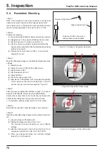
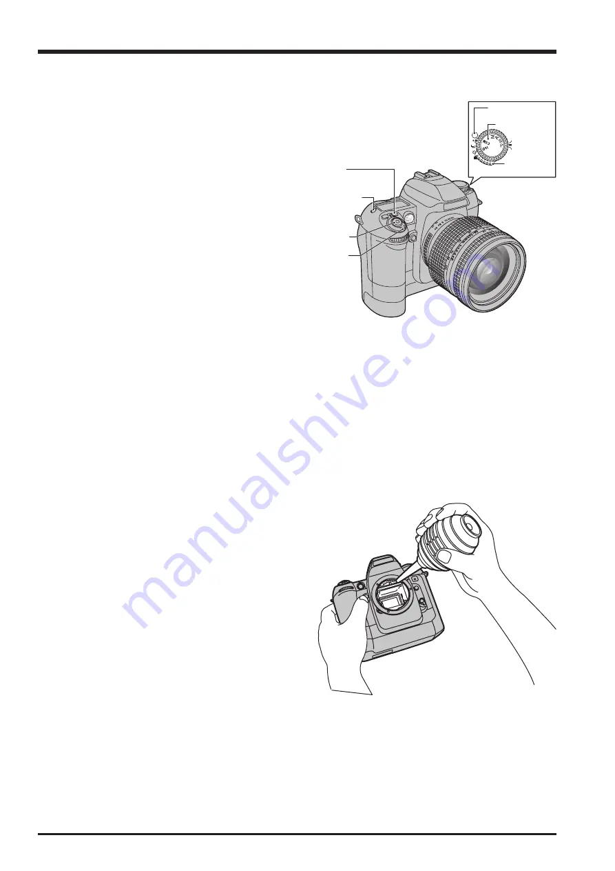
<Fig. 5-5-1> Various button charts
<Fig. 5-5-2> Appearance of blower cleaning
This camera is fitted with a CCD as its imaging (pickup) element.
The CCD is located behind the shutter. Dust or other soiling
may stick to the CCD and, depending on the photography
settings and the type of subject, may be visible in photographed
images if it is not cleaned off. If this occurs, the CCD needs to
be cleaned.
[Note]
Always use the AC power adapter when performing this task.
Loss of power during cleaning could cause the mirror to drop
or the shutter to close, risking damage to the camera.
5-5-1.
CCD Cleaning Using a Visual Inspection
for Dusting
<Step 1>
Check that the camera is switched off and remove the lithium
batteries.
<Step 2>
Connect the AC power adapter to the camera.
<Step 3>
Remove the interchangeable lens from the camera.
<Step 4>
Set the camera’s exposure mode dial to “M”.
<Step 5>
Hold down the release mode switch lock release button and
set the release mode switch to “S1 Frame”.
<Step 6>
Hold down the Synchro mode and Illuminator buttons and switch
the camera on.
<Step 7>
When you press the shutter button, the mirror stays up and the
shutter stays open.
<Step 8>
Hold the camera so that light shines on the CCD (OLPF) and
check for soiling on the CCD surface either visually or using a
stereoscopic microscope. If soiling is found, use a blower to
remove it ([Note]).
If the soiling cannot be removed using the blower, wipe the
CCD with a lens cleaner or lint-free cloth and EE cleaner or
ethanol (95% or higher).
Do not use a blower with a brush attached. Using a blower-
brush to clean the CCD can scratch the CCD surface.
[Note]
When using a lens cleaner to wipe the CCD, note that any
metallic residue on the CCD (OLPF) surface will cause
scratches in the CCD surface during cleaning.
Exposure compensation
button
LCD illuminator
button
Shutter button
Power switch
Release mode
switch
Exposure mode dial
Release mode switch
unlock button
Summary of Contents for FinePix S3Pro
Page 27: ...27 3 Schematics FinePix S3Pro Service Manual 3 6 Circuit Diagrams 3 6 1 CCD BLOCK ...
Page 28: ...28 3 Schematics FinePix S3Pro Service Manual 3 6 2 DCDC BLOCK ...
Page 29: ...29 3 Schematics FinePix S3Pro Service Manual 3 6 3 IEEE1394 BLOCK ...
Page 30: ...30 3 Schematics FinePix S3Pro Service Manual 3 6 4 PROCESS BLOCK ...
Page 31: ...31 3 Schematics FinePix S3Pro Service Manual 3 6 5 CARD BLOCK 3 6 6 DCDC BLOCK CAMERA BODY ...
Page 32: ...32 3 Schematics FinePix S3Pro Service Manual 3 6 7 PARTNER CHIP BLOCK ...
Page 33: ...33 3 Schematics FinePix S3Pro Service Manual 3 6 8 PWON BLOCK ...
Page 34: ...34 3 Schematics FinePix S3Pro Service Manual 3 6 9 USB2 0 BLOCK ...
Page 35: ...35 3 Schematics FinePix S3Pro Service Manual 3 6 10 LCD BLOCK ...
Page 36: ...36 3 Schematics FinePix S3Pro Service Manual 3 6 11 SW BLOCK ...
Page 38: ...38 3 Schematics FinePix S3Pro Service Manual 3 7 2 MAIN PWB ASSY SIDE A ...
Page 39: ...39 3 Schematics FinePix S3Pro Service Manual SIDE B ...
Page 40: ...40 3 Schematics FinePix S3Pro Service Manual 3 7 3 SW PWB ASSY SIDE A SIDE B ...
Page 102: ...26 30 Nishiazabu 2 chome Minato ku Tokyo 106 8620 Japan FUJI PHOTO FILM CO LTD ...


