2.4 Specifications of Components
2-17
1
2
3
4
5
6
7
8
9
10
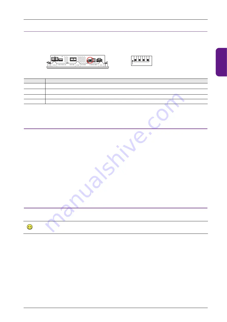
2.4.8 DIP Switches
The unit is equipped with DIP switches 1 to 4. Turn off power to the unit before changing any DIP switches.
Upon delivery, all DIP switches are set to OFF.
*1 The System Configurator is displayed if No. 1 and No. 2 are both set to the ON position.
DIPSW1: Storage Automatic Upload
A screen program can be automatically uploaded from a USB flash drive.
* This function is valid when HMI is selected as the startup mode on System Configurator.
Procedure
1. Use the V-SFT-6 editor to load a screen program onto a storage device.
(For the loading procedure, refer to the X1 Series Reference Manual 2.)
2. Turn off the X1 series unit power and connect the USB flash drive.
3. Set DIP switch 1 to the ON position.
4. Turn ON the X1 series unit power. The screen program is automatically loaded into the flash memory of the X1 series unit.
* When not using automatic upload, always set DIP switch 1 to OFF.
If DIP switch 1 is set to ON and the X1 series unit power is turned on without a storage device connected, the message “Insert Storage
in X1” is displayed.
DIPSW2: Display of Touch Switch Test Screen
The touch switch test screen can be displayed.
Procedure
1. Turn off the X1 series unit power.
2. Set DIP switch 2 to the ON position.
3. Turn on the X1 series unit power. The touch switch test screen is displayed. Check if touch switches are functioning properly.
* Press the [Return] switch on the touch switch test screen to return to either the X1 app or System Configurator. Note that the touch
switch test screen will be displayed again if the power is turned off and on again. When not using the touch switch test screen, always
set DIP switch 2 to OFF.
No.
Specifications
1
*1
Storage automatic upload
2
*1
Display of touch switch test screen
3
Terminating resistance of transmitting line for serial communcation RS-422 (4-wire connection) / RS-485 (2-wire connection)
4
Terminating resistance of receiving line for serial communication RS-422 (4-wire)
The touch switch test screen can also be displayed by either of the following methods:
- X1 app Local mode
[I/O Check]
- System Configurator
[Touch operations check]
Bottom view
1 2 3 4
ON
Enlarged view
Summary of Contents for MONITOUCH X1 Series
Page 1: ...Series Hardware Specifications...
Page 3: ......
Page 5: ......
Page 9: ......
Page 13: ......
Page 14: ...1 Product Outline 1 1 Features 1 2 Models and Peripheral Equipment 1 3 System Configuration...
Page 15: ......
Page 19: ...1 Product Outline 1 4...
Page 21: ......
Page 40: ...3 Installation 3 1 Installation 3 2 Power Supply 3 3 Securing USB and HDMI Cables 3 4 Battery...
Page 41: ......
Page 51: ...3 Installation 3 10...
Page 53: ......
Page 59: ......
Page 162: ...6 Errors 6 1 Errors 6 2 Troubleshooting...
Page 163: ......
Page 173: ...6 Errors 6 10...
Page 174: ...7 Inspection and Maintenance 7 1 Inspection and Maintenance 7 2 Warranty Policy...
Page 175: ......
Page 179: ...7 Inspection and Maintenance 7 4...


