background image

5 Operation Method

5-44

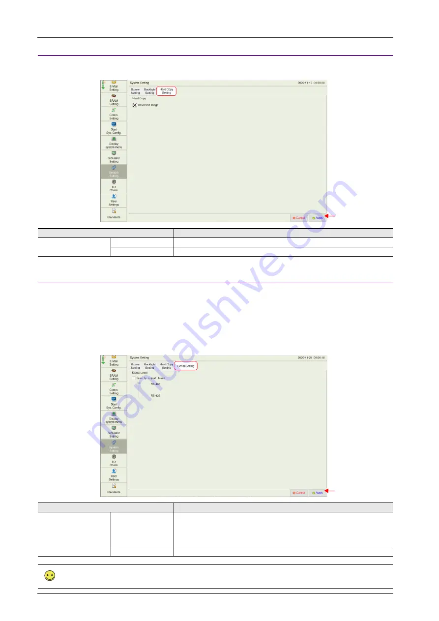
Hard Copy Setting

The [Hard Copy Setting] tab window on the System Setting screen is used to change the hard copy setting.

Serial Setting

The [Serial Setting] tab window on the System Setting screen is used to set the signal level for serial communication (RS-422/RS-485).
This setting is necessary when all of the following three conditions apply.

• The [Target Port No.] is set to [SERIAL] for PLCx in the [Hardware Setting] window of a screen program.
• The [Signal Level] setting is set to [RS-422/485] at either of the following locations:

[Hardware Setting] 

 [PLCx Properties] in the screen program

[Comm. Setting] 

 [Communication Parameter] in Local mode

• A connected device supports both RS-485 (2-wire connection) and RS-422 (4-wire connection) and RS-422 is used for connection.

Item

Description

Reversed Image

Unselected

Black and white are not inverted.

Selected

Black and white are inverted.

Item

Description

Specify signal level

Unselected

Automatic recognition

• On models that support RS-485 (2-wire connection) only, RS-485 is used for connection.

• On models that support RS-422 (4-wire connection) only, RS-422 is used for connection.

• On models that support both RS-485 (2-wire connection) and RS-422 (4-wire 

connection), RS-485 is used for connection.

Selected

Select either RS-485 (2-wire connection) or RS-422 (4-wire connection).

This setting is invalid when [Signal Level] is set to [RS-232C].

[Hard Copy Setting] tab window

Press the [Apply] switch 

to confirm the settings.

[Serial Setting] tab window

Press the [Apply] switch 

to confirm the settings.

Summary of Contents for MONITOUCH X1 Series

Page 1: ...Series Hardware Specifications...

Page 2: ...numbers are shown at the bottom left corner on the back cover of each manual Printing Date Reference No Revised Contents December 2020 2024NE0 First edition December 2021 2024NE1 Second edition Octob...

Page 3: ......

Page 4: ...created screen program using V SFT version 6 1092NE X1 Series Hardware Specifications this manual Explains precautions for handling hardware specifications and operating procedures and provides an er...

Page 5: ......

Page 6: ...en it is unpacked Do not use the unit if any damage or deformation is found Failure to do so may lead to fire damage or malfunction For use in a facility or as part of a system related to nuclear ener...

Page 7: ...ations of the countries concerned Ask your forwarding agent for details of transport regulations Notes on the LCD Note that the following conditions may occur under normal circumstances The response t...

Page 8: ...Make sure to thoroughly check the operation before actual use Hakko Electronics shall not be held responsible for dealing with trouble or liable for damages stemming from Microsoft products while usi...

Page 9: ......

Page 10: ...LAN LAN2 2 9 2 4 2 SERIAL 2 10 2 4 3 USB A 2 11 2 4 4 HDMI 2 13 2 4 5 Audio Output 2 13 2 4 6 WLAN 2 14 2 4 7 Bluetooth 2 16 2 4 8 DIP Switches 2 17 3 Installation 3 1 Installation 3 1 3 1 1 Mounting...

Page 11: ...ting 5 42 5 4 15 Storage Transfer 5 45 5 4 16 I O Check 5 54 5 4 17 User Settings 5 57 5 4 18 Standards Only for Wireless LAN I F Models 5 62 5 4 19 Handling Data Changed in Local Mode 5 63 5 5 System...

Page 12: ...the Event of an Error 6 8 6 2 2 Probable Symptoms 6 8 7 Inspection and Maintenance 7 1 Inspection and Maintenance 7 1 7 1 1 Daily Inspection 7 1 7 1 2 Periodical Inspection 7 1 7 2 Warranty Policy 7...

Page 13: ......

Page 14: ...1 Product Outline 1 1 Features 1 2 Models and Peripheral Equipment 1 3 System Configuration...

Page 15: ......

Page 16: ...e expandability By adopting a Window OS various software can be used without interfering with the existing human machine interface HMI function 5 Vector rendering Instead of bitmap rendering vector fo...

Page 17: ...iption V SFT 6 Screen configuration software Application software for editing screen programs Supported OS Windows Vista 32bit 64bit 7 32bit 64bit 8 32bit 64bit 8 1 32bit 64bit 10 32bit 64bit 11 64bit...

Page 18: ...B A Bluetooth 1 2 WLAN 1 X1 V9 AUDIO X1 KEYPAD CONTROL PRO MODE Hz KW A RUN STOP PRG RESET FUNC DATA Inverter Screen configuration software Screen creation PLC general purpose computer Computer PC Dis...

Page 19: ...1 Product Outline 1 4...

Page 20: ...2 Specifications 2 1 Specifications 2 2 External Dimensions and Panel Cut out Dimensions 2 3 Names of Components 2 4 Specifications of Components...

Page 21: ......

Page 22: ...or less 6 ms ambient temperature at 25 C Withstand Voltage DC external terminals to FG 500 VAC for 1 minute Insulation Resistance DC external terminals to FG 500 VDC 10 M or higher Physical Environme...

Page 23: ...Item X1121iSD X1121iSRD X1151iSD X1151iSRD Hardware Processor Intel Atom x5 E3940 Cores Threads 4 4 Main Memory 4GB Internal storage SSD 64 GB Free space 30 GB 1 Software OS Windows 10 IoT Enterprise...

Page 24: ...Number of Ports 2 Baud Rate Low speed 1 5 Mbps Full speed 12 Mbps High speed 480 Mbps Super speed 5 0 Gbps Applications Printer USB flash drive keyboard mouse connection etc USB A Ver 2 0 Number of P...

Page 25: ...soft NET Framework 4 0 or 4 5 If a PC does not have NET Framework 4 0 or 4 5 installed Framework 4 0 will be automatically installed on the PC Item Specification Interface Language 1 Japanese English...

Page 26: ...lay Max 4 096 1 per screen Character Display Max 4 096 1 per screen Message Display Max 4 096 1 per screen Maximum number of characters per line 127 one byte characters Message Max 32 768 lines Macro...

Page 27: ...ions 2 6 2 2 External Dimensions and Panel Cut out Dimensions 2 2 1 X1121 58 7 8 0 230 0 0 5 0 309 0 0 5 0 66 7 229 0 308 0 241 0 320 0 Panel cut out dimensions Rear view Bottom view Front view Side v...

Page 28: ...imensions and Panel Cut out Dimensions 2 7 1 2 3 4 5 6 7 8 9 10 2 2 2 X1151 271 0 406 0 260 0 0 5 0 395 0 0 5 0 259 0 394 0 60 2 8 0 68 2 Panel cut out dimensions Rear view Bottom view Front view Side...

Page 29: ...omes extremely hot 7 Cable clamp hole Used to fix USB and HDMI cables in place 8 USB 2 0 USB version 2 0 Type A port 2 channels 9 USB 3 0 USB version 3 0 Type A port 2 channels 10 HDMI External monito...

Page 30: ...cations Screen program transfer PLC connection upper layer PC connection printer connection etc LAN Pin No 10BASE T 100BASE TX 1000BASE T 1 TX Transmit signal BI_DA Transmit receive data A 2 TX Transm...

Page 31: ...nit Recommended cable AWG 26 stranded wire braided shield Check the operation in advance in the usage environment Item Specification Number of Ports 1 Connector RJ 45 Communication Standard RS 232C RS...

Page 32: ...Function is required For details refer to the X1 Series Reference Manual 1 Item USB A Ver 2 0 USB A Ver 3 0 Number of Ports 2 Port 3 Port 4 2 Prot 1 Port 2 Baud Rate Low speed 1 5 Mbps Full speed 12 M...

Page 33: ...ies Reference Manual 2 Mouse Connection A mouse can be used for screen operations by connecting a mouse to the X1 series unit The screen of the multi display function also can be operated Connection e...

Page 34: ...lly if any cable without ferrite cores is used Images may not be displayed normally if the cable length exceeds 5 meters Use a device and cable that conforms to standard HDMI specifications 2 4 5 Audi...

Page 35: ...ion indicating a higher RSSI value will attain a more stable communication status A low RSSI value which cannot be improved by moving the access point indicates that the radio wave intensity is attenu...

Page 36: ...nce to a certain low power radio station for identifying moving objects or if any other problem occurs contact your local sales representative 4 Communications conforming to IEEE802 11ac IEEE802 11n o...

Page 37: ...pecifications Item Specification Number of Ports 1 Supported Standards V2 1 EDR V3 0 HS V4 0LE V4 1 V4 2 V5 0 Supported Class Class1 Transfer Speed Low Energy 2 Mbps Enhanced data rate EDR 3 Mbps Freq...

Page 38: ...X1 series unit power is turned on without a storage device connected the message Insert Storage in X1 is displayed DIPSW2 Display of Touch Switch Test Screen The touch switch test screen can be displa...

Page 39: ...e sure to set DIP switch 1 and 2 to the OFF position DIPSW3 4 Terminating Resistance Setting Set the terminating resistance for serial communication When connecting a controller via RS 422 4 wire conn...

Page 40: ...3 Installation 3 1 Installation 3 2 Power Supply 3 3 Securing USB and HDMI Cables 3 4 Battery...

Page 41: ......

Page 42: ...rovided fixtures into the mounting holes on the X1 series unit 8 positions three each on the top and bottom and one each on the left and right and fix the unit in place with the tightening screws tigh...

Page 43: ...can be mounted in the following orientation Mounting Angle Install the unit within the following angle range Panel Cut out Dimensions Model X Y Z Panel thickness X1121iS 309 0 230 0 1 5 to 4 0 X1151iS...

Page 44: ...Mount the X1 series unit with approximately 100 mm of space around the periphery of the unit Ambient Temperature Use the X1 series unit in an ambient temperature range of 0 C to 45 C wet bulb temperat...

Page 45: ...he ends of wires Doing so may lead to poor contact When using stranded wire for cabling make sure that the core is sufficiently twisted Otherwise stray wires may cause a short circuit with neighboring...

Page 46: ...grounding cables The signal ground SG and frame ground FG are connected inside the X1 series unit Always ground the X1 series unit The level of grounding resistance should be 100 or less X1 series uni...

Page 47: ...X1 series unit depending on the mounting conditions Use the cable ties provided with the unit to prevent disconnection 3 3 1 Securing Cables Example USB cable 1 Pass a cable tie through the lower sid...

Page 48: ...forming battery replacement Use the designated battery for replacement Rough handling of the battery may cause fire or chemical burns Observe local and governmental regulations when disposing of waste...

Page 49: ...nd fully insert the battery into the battery holder 7 Mount the cover by first aligning the bottom edge and then setting the entire cover in place 8 Attach the screws 8 positions removed in step 3 at...

Page 50: ...not contained in or packed with equipment and classified as non dangerous goods Transportation of batteries containing lithium metal must observe the relevant transport regulations Batteries are pack...

Page 51: ...3 Installation 3 10...

Page 52: ...4 X1 Setup Procedures 4 1 Procedure before Operation 4 2 Setting Procedure For a new unit 4 3 Setting Procedure For an existing unit...

Page 53: ......

Page 54: ...nd transfer the program to the X1 series unit via Ethernet 7 Start operation When a connection with controllers has been established the X1 series unit enters RUN mode If the X1 series unit does not o...

Page 55: ...rn power on System Configurator 5 5 System Configurator page 5 66 Language change Time settings IP address setting Set Startup settings operation mode to HMI HMI app starts Write filter setting Valid...

Page 56: ...5 4 1 Switching to Local Mode page 5 17 IP Address Setting page 5 69 Startup Settings Operation Mode page 5 81 5 5 System Configurator page 5 66 Check the IP address Using the IP address as is Changi...

Page 57: ...ng is set to Valid some System Configurator settings cannot be changed If a setting cannot be changed set Write filter setting to Invalid and then change the intended setting For details refer to Sett...

Page 58: ...5 Operation Method 5 1 Overview 5 2 System Menu and Status Bar 5 3 RUN Mode 5 4 Local Mode 5 5 System Configurator...

Page 59: ......

Page 60: ...with connected device is stopped This mode screen shows various information about the X1 series unit such as system information screen program information etc page 5 16 System Configurator For configu...

Page 61: ...hing to Local Mode 3 System menu RUN switch 4 Turn power off and back on again Only when System Configurator Settings Startup settings is set to HMI 5 Operation test Start HMI app 6 Turn power off and...

Page 62: ...o display the system menu If any of the items given below are placed in a corner on the screen the system menu will not be displayed Be sure to press a corner where none of the items are placed If the...

Page 63: ...ference Manual 2 Login Logout Displays the login logout screen User Settings Displays the administrator authentication screen On the user list screen a new user account can be added and the registered...

Page 64: ...ff before removing the storage device If using the macro commands COPY_FILE MOVE_FILE DEL_FILE READ_FILE WRITE_FILE be sure to check that s1050 4 is turned off before removing the storage device While...

Page 65: ...t is made the message Level does not match appears Logout This section explains the logout procedure for a user at security level 4 1 Display the system menu press Security in the system menu and pres...

Page 66: ...ayed Enter an administrator name and password and press the OK switch 3 Registered user accounts are listed as shown below When the Security switch in the system menu is pressed the system menu is hid...

Page 67: ...x The user name must be unique The same password can be set for multiple users 3 Press the OK switch to add the user account to the list Administrator privileges Operations that can be performed on th...

Page 68: ...h 2 The confirmation dialog shown below is displayed To delete press the OK switch 3 The selected user account is deleted from the list Only accounts registered on MONITOUCH can be deleted Accounts re...

Page 69: ...itch 2 Change the settings 3 After change press the Apply or OK switch The settings are updated Only accounts registered on MONITOUCH can be edited Accounts registered in the screen program cannot be...

Page 70: ...seconds to display the status bar If any of the items given below are placed in a corner on the screen the system menu will not be displayed Be sure to press a corner where none of the items are place...

Page 71: ...ight end of the status bar Upon the elapse of 15 seconds from when the status bar was displayed The status bar is not hidden if the push pin icon is pressed always display or when displaying detailed...

Page 72: ...ile the status bar is displayed The status bar has priority over scrolling messages displayed at the bottom of the screen The status bar and system keyboard cannot be displayed at the same time The sy...

Page 73: ...cons indicate the status of communication with a connected device when Comm Error Handling Disconnect is selected When the PLC 8WAY Connection Status icon is pressed with no link established the detai...

Page 74: ...5 3 RUN Mode The RUN mode is for communicating with an upper layer computer PLC etc A screen program created using the V SFT version 6 configuration software needs to be transferred to the X1 series u...

Page 75: ...information etc is displayed Also this mode functions as a system screen for transferring a screen program between a computer and the X1 series unit Menu icons can be scrolled up and down Title of th...

Page 76: ...items given below are placed in a corner on the screen the system menu will not be displayed Be sure to press a corner where none of the items are placed If these items are placed in all four corners...

Page 77: ...5 Operation Method 5 18 Method 2 created switch Press a switch with Function set to Switching to Local Mode Select...

Page 78: ...e 5 27 WLAN Setting only for models with wireless LAN IP Setting page 5 28 Option page 5 29 E Mail Setting 1 Connection Setting page 5 30 Option page 5 31 SRAM Setting page 5 34 Comm Setting Communica...

Page 79: ...0 5 4 3 RUN Pressing RUN in the menu icons switches to RUN mode 1 The splash screen can be changed as desired For details refer to the X1 Series Reference Manual 2 Menu icons Splash screen 1 RUN scree...

Page 80: ...ation of the X1 series unit Item Description Model Information Model Indicates the model of the X1 series unit Program Ver Indicates the program version OSVer Blank Ethernet Information LAN IP Address...

Page 81: ...splayed Expand display screen Displayed only when Expand display screen is selected at System Setting Other Multi Display Settings using V SFT version 6 Shows whether main or sub apps are displayed Ma...

Page 82: ...8 Maker Indicates the manufacturer of the connected device Model Indicates the model name of the connected device Ver driver file name Indicates the version of the communication I F driver and its fil...

Page 83: ...e Setting tab window is applied to the following screens Item Description Language Setting Select an interface language English Japanese Traditional Simplified Korean Local mode Messages at the bottom...

Page 84: ...Mask Indicates the subnet mask of the LAN port Gateway Indicates the default gateway of the LAN port MAC Address Indicates the MAC address of the LAN port External Access Service Port Set the port nu...

Page 85: ...or 255 broadcast address Example 128 0 255 255 192 168 1 0 Port Number Multiple applications are running on each node and communications are carried out for each application between the nodes Consequ...

Page 86: ...ch to confirm the settings Adding procedure 1 Press LAN Setting LAN2 Setting in the menu icons and open the Network Table Edit tab window 2 Press the Add switch 3 Press each item and input settings us...

Page 87: ...ess LAN is turned on enabled but a link is not established The wireless LAN is turned on enabled but not connected to the specified access point IP Setting The IP Setting tab window shows the wireless...

Page 88: ...imeout period to be used for the EREAD EWRITE SEND and MES macro commands and Ethernet DLL functions Retrials Fixed to 0 The IP address of the X1 series unit is set on System Configurator Refer to pag...

Page 89: ...am When the Restore Screen Data Settings switch is pressed settings made in the Connection Setting and Mail Setting tab windows are canceled and those in the screen program are restored When settings...

Page 90: ...on POP before SMTP is selected Set the POP3 IP address Use SSL TLS Communication Displayed when Authentication SMTP AUTH is selected Select this checkbox when using SSL TLS communications Account Name...

Page 91: ...ndow 2 Select a mail address to edit and press the Change switch 3 Pressing each setting field brings up the system keyboard to be used for configuration Set the recipient mail address When No is chan...

Page 92: ...8 9 10 Deleting the recipient mail addresses 1 Press E Mail Setting in the menu icons and open the Mail Setting tab window 2 Select a mail address to delete and press the Delete switch 3 Press the Ap...

Page 93: ...is different from the one configured in the SRAM Clock Setting window of V SFT version 6 the SRAM Setting menu icon is changed as shown below The following area in the X1 series unit is the SRAM area...

Page 94: ...ternal device memory L etc is completely cleared Double check before formatting the SRAM 1 Press SRAM Setting in the menu icons The SRAM Setting screen is displayed 2 Press the Format switch and the E...

Page 95: ...the display of the communication settings between PLC1 to PLC8 If only PLC1 is used the display cannot be changed over Restore Screen Data Settings Restores communication settings that were changed on...

Page 96: ...specific communication parameter for PLCx press and switches to select the connected device targeted for restoration 3 Press the Restore Screen Data Settings switch The following dialog box appears To...

Page 97: ...ication parameter on the X1 series unit 1 For details refer to the X1 Series Connection Manual Signal Level Baud Rate Data Length Parity Stop Bit Stat No Local Port No Time Out Retrials Send Delay Tim...

Page 98: ...plays the station name set in the screen program Cannot be changed IP Address Set the IP address for the connected device Port No Set the port number of the connected device Item Description Transmiss...

Page 99: ...plays System Configurator This switch is valid when the X1 series unit is started with System Configurator Startup mode selection set to System Configurator and the X1 app is started from System Confi...

Page 100: ...thernet UDP IP Address Set the IP address for the connected computer Default 192 168 1 201 Service Port Set the port number for the simulator Default 8020 Set the same number as the one set for File C...

Page 101: ...the screen program When this switch is pressed while the Buzzer Setting or Backlight Setting tab window is open settings in the current tab window are cancelled and those in the screen program are re...

Page 102: ...the backlight control setting For details on the difference between these actions refer to the X1 Series Reference Manual 1 AUTO 1 AUTO 2 AUTO 3 Manual Backlight OFF Time This item can be set only wh...

Page 103: ...d device supports both RS 485 2 wire connection and RS 422 4 wire connection and RS 422 is used for connection Item Description Reversed Image Unselected Black and white are not inverted Selected Blac...

Page 104: ...scription Transfer Menu Display Storage Transfers data from a storage device to the X1 series unit Display Storage Transfers data from the X1 series unit to a storage device Display Storage Compares s...

Page 105: ...and reinsert the USB storage from this point on 3 Target storage device selection Select W USB under Storage to Connect 4 Transfer operation selection Select the transfer operation and press the OK sw...

Page 106: ...evice and the folder name When the selected folder is all right proceed to step 4 To change the folder proceed to step 3 3 Access folder change showing folders in the storage To change the access fold...

Page 107: ...nsfer 5 Data transfer completed When the data has been transferred successfully the following message dialog is displayed Press the OK switch The System Information screen is automatically displayed o...

Page 108: ...ritten If the Storage File Information field is blank a new file DSP0000 BIN will be created in the DSP folder under the access folder When selecting Use Password When Transferring Screen to storage f...

Page 109: ...ch changes to Transferring and the Transferring data Storage dialog is displayed On successful completion the Work normally finished dialog is displayed Press the OK switch If any other message is dis...

Page 110: ...art switch changes to Transferring and the Transferring data Storage dialog is displayed On successful completion the Work normally finished dialog is displayed Press the OK switch If any other messag...

Page 111: ...the following dialog is displayed 2 Execution of data delete to during execution Press the OK switch if deleting all data from storage 3 Data deletion completed When the data has been completely delet...

Page 112: ...over Cannot write data to a storage device because the data size in the X1 series unit is larger than the capacity of the storage device Selected data does not exist The data does not exist in the re...

Page 113: ...ng using V SFT version 6 Item Description Touch Switch Test Switches to the touch switch test screen For the test procedure refer to page 5 55 USB Storage Connection Status W X Y Z drive 1 Indicates t...

Page 114: ...ds appear on the screen as shown below 3 Checking the switch output state Press a position on the screen and check if the pressed position turns white If the pressed position turns white the switch is...

Page 115: ...heck in the menu icons and open the Network test tab window 2 Press the IP Selection field The system keyboard appears Enter the IP address of the counterpart device targeted for a connection test 3 P...

Page 116: ...Security Only Select a criterion to display specific users in the user list All All user names are listed Security Only Only users who are granted security privileges with a security level set are lis...

Page 117: ...screen for administrator authentication is displayed Enter an administrator name and password and press the OK switch Administrator Mode is displayed on the screen If the User Settings screen is switc...

Page 118: ...f 8 one byte alphanumeric characters case sensitive can be used for a user name or password The user name must be unique The same password can be set for multiple users To grant administrator privileg...

Page 119: ...accounts that can be deleted The account of an administrator user that is currently logged in User accounts which were registered on MONITOUCH Registered in Main unit and are not granted administrator...

Page 120: ...e registered on MONITOUCH Registered in Main unit and are not granted administrator privileges User accounts that cannot be edited The account of users granted administrator privileges other than the...

Page 121: ...llowing two conditions 1 this device may not cause interference and 2 this device must accept any interference including interference that may cause undesired operation of this device Le pr sent appar...

Page 122: ...e INI file using V SFT version 6 1 Cable connection Connect the X1 series unit to a computer using a LAN cable 2 Starting V SFT version 6 Start V SFT version 6 on the computer and open the screen prog...

Page 123: ...series unit register a password for cancellation Click Prohibition Cancel Setting and select the Request a password to cancel the prohibition checkbox and register a password maximum of 16 one byte a...

Page 124: ...password 2 Press the Apply switch The following confirmation dialog appears Press the OK switch All items that were prohibited in Local mode become unprotected 3 To validate the Local mode prohibitio...

Page 125: ...ay brightness setting page 5 80 Startup settings operation mode page 5 81 Time settings Calendar Time zone Internet time page 5 82 Security Setting page 5 84 Printer Setting page 5 88 Sound Settings p...

Page 126: ...es are not possible when Write filter setting is set to Valid Set Settings Write filter setting to Invalid Refer to Write Filter Setting page 5 75 Public Path Description C drive C Userdata An area th...

Page 127: ...elete is selected a confirmation window appears Sorting pasting undoing redoing creating a new folder Hold down an area in the file folder view other than a folder or file icon A pop up menu will be d...

Page 128: ...Windows system settings IP Address Setting This screen is used to set and check the IP address of the LAN LAN2 and WLAN ports Settings cannot be changed when Write filter setting is set to Valid Set S...

Page 129: ...the alternate DNS server Speed and duplex Set the speed and duplex mode Auto negotiation default Automatic setting through correspondence with the connected device 10 Mbps half duplex 10 Mbps bidirec...

Page 130: ...nit operates in station mode Station Mode The Windows Wi Fi setting menu is used 1 Set WLAN to On Displaying and setting changes are not possible when Write filter setting is set to Valid Set Settings...

Page 131: ...ect the respective SSID and then press Connect 3 Input the security key Setting is complete when a connection is established Methods for inputting numbers and text Use the System Configurator System k...

Page 132: ...e For the operation method of a smart device refer to the operation manual of the device 2 Display the Bluetooth settings screen on the X1 series unit 3 Set Bluetooth to On 4 Select Add Bluetooth or o...

Page 133: ...evice is ready to go is displayed Press Done to return to the System Configurator screen Connecting with a Registered Device A smart device registered for pairing will automatically be connected by tu...

Page 134: ...setting changes are attempted with Write filter setting set to Valid writing prohibited Write Filter Setting Item Description Write filter setting This setting is used to prohibit writing to the inte...

Page 135: ...stem Configurator Setting Startup settings Shutdown operation When Write filter setting is set to Invalid be sure to press the Shutdown switch in System Configurator Turn the power off 15 seconds afte...

Page 136: ...r setting Valid is selected Even if you change the screen program or update the file the X1 will return to the state before the change by turning the power off and back on again or rebooting Available...

Page 137: ...splay the operation screen Function Access Retention using external USB storage Screen program transfer to the X1 series unit Editor 1 Internal storage Disabled Storage Transfer 2 Disabled Automatic U...

Page 138: ...witch is pressed Wi Fi settings Station Disabled Disabled Bluetooth settings Disabled Disabled Write filter setting Enabled Enabled Reboot after setting change Display brightness setting Enabled Enabl...

Page 139: ...lter setting is set to Valid Set Settings Write filter setting to Invalid Refer to Write Filter Setting page 5 75 The setting can also be changed by displaying the system menu in RUN Local mode and pr...

Page 140: ...e X1 series unit automatically reboots when the setting is changed The mode specified here starts after rebooting When the setting is changed from System Configurator to HMI the Write filter setting i...

Page 141: ...Time Indicates the current time Change date time Manually change the date and time setting Refer to page 5 82 Time zone Indicates the time zone Change time zone Specify a time zone The time is automa...

Page 142: ...1 series unit power on Item Description Use internet time Select to acquire the time from an internet time server Time server Input the computer name or IP address of the NTP server for synchronizing...

Page 143: ...curity method that utilizes a whitelist to define the programs that a user can run on a computer All applications other than those that have been confirmed to be safe by the administrator are blocked...

Page 144: ...bled An application installed in this state is automatically added to the whitelist The list is updated once every 30 minutes To immediately update the list press the Security Setting Adding to list U...

Page 145: ...n and the execution result is displayed Adding to the list takes time In addition all other operations are disabled during the process Execute list addition after completing all other system settings...

Page 146: ...y Setting and then set Mode setting to Updating mode The X1 series unit automatically reboots 4 Install the user application 5 Press Security Setting Adding to list Update list The application is adde...

Page 147: ...e printer driver exe file or data from the CD supplied with the printer to a USB flash drive and install via Explorer refer to 5 5 2 Explorer page 5 67 For details on installation refer to the instruc...

Page 148: ...5 5 System Configurator 5 89 1 2 3 4 5 6 7 8 9 10 2 Select the printer to set as default from the printers scanners list and press Manage 3 Press Set as default...

Page 149: ...evice can be selected when connecting an external speaker 5 5 4 Storage Management This screen shows the capacity of the internal storage SSD Settings cannot be changed when Write filter setting is se...

Page 150: ...ows the task list icon in the foreground at all times The icon is also displayed while the X1 app is displayed Double tap the icon to display a list of applications Hide Hides the task list icon If us...

Page 151: ...scription HMI Indicates the HMI program version Hardware Indicates the hardware revision System Configurator Indicates the System Configurator version BIOS Indicates the BIOS version EC Indicates the...

Page 152: ...ed The icon is also displayed while the X1 app is displayed The system keyboard is displayed in the foreground by double tapping the icon Pressing x returns the keyboard display to an icon Text can al...

Page 153: ...g does not apply to the HMI screen The interface langauge of the HMI screen can be changed in Local mode However for a brand new X1 series unit this setting also applies to the HMI screen Item Descrip...

Page 154: ...Operation check Displays a screen for checking that the touch switches operate properly The same screen can also be displayed by the following methods Local mode I O Check Touch Switch Power on option...

Page 155: ...gs Setup 2 The following window is displayed on the X1 series unit Press the Enter key on the keyboard to proceed 3 The same screen is displayed on the external display Tap the screen according to the...

Page 156: ...Configurator Start HMI App Press this switch to display the X1 Local mode screen without exiting System Configurator Item Description Start HMI app Displays the X1 Local mode screen without exiting Sy...

Page 157: ...Exit System Configurator Press this switch to exit System Configurator and return to the X1 Local mode screen This switch is disabled when Settings Startup settings Startup mode selection is set to S...

Page 158: ...ed when Write filter setting is set to Valid Set Settings Write filter setting to Invalid Refer to Write Filter Setting page 5 75 Any failure resulting from operations done in advanced mode are not co...

Page 159: ...n the System Configurator Setting Startup settings Exiting the Windows Desktop Display Run the Shutdown shortcut on the desktop to shut down the X1 operating system The power lamp remains lit and the...

Page 160: ...goes out Be sure to press the Shutdown switch if Write filter setting is set to Invalid If the power is turned off without pressing the Shutdown switch the file system may become damaged and recovery...

Page 161: ...5 Operation Method 5 102 5 5 13 Reboot Reboot the X1 series unit RUN screen or System Configurator...

Page 162: ...6 Errors 6 1 Errors 6 2 Troubleshooting...

Page 163: ......

Page 164: ...g to the error message When the Retry switch is pressed the operation mode switches to RUN mode 6 1 2 Screen Program Error When an error is found in the screen program the following message is display...

Page 165: ...Hardware Setting Target Settings PLC Table 47 IDs of the items having setting limitations in the screen library are duplicated on a screen Check the IDs and keep them unique 49 Group ITEM error Conta...

Page 166: ...r function and transfer the screen program again 160 The SRAM area size exceeds the available range Check the settings in the System Setting Unit Setting SRAM Clock Setting window 161 The SRAM area is...

Page 167: ...ings is set to Yes and the data specified for Editing Screen Main is being transferred to the sub app sub screen only Transfer to the main app at Transfer Communication Setting Option Port No 8001 Whe...

Page 168: ...en Comm Error handling Continue is selected The communication error message will be displayed at the center of the screen The same communication will continue until restoration and screen operation is...

Page 169: ...the controller error code and solve the problem Breakage detected The controller s SD remains at the low level Examine the connection between the controller s SD and the X1 s RD Invalid memory Mitsub...

Page 170: ...he communication lines Cannot establish TCP connection Connection cannot be established Check the communication lines or turn the power off and back on again TCP Communication Error TCP communication...

Page 171: ...d by all screens such as a control area System Setting Hardware Setting Control Area logging server alarm server and initial macro specified in V SFT version 6 1 Check if any address outside the permi...

Page 172: ...h functions etc on V SFT version 6 2 Execute Touch operations check Calibration in System Configurator Refer to page 5 96 3 Return the unit to your local distributor The screen program cannot be trans...

Page 173: ...6 Errors 6 10...

Page 174: ...7 Inspection and Maintenance 7 1 Inspection and Maintenance 7 2 Warranty Policy...

Page 175: ......

Page 176: ...ironment is hot humid or dusty 7 1 2 Periodical Inspection Inspect the following points periodically Are the ambient temperature and humidity appropriate 0 to 45 C 85 RH or less Are the environmental...

Page 177: ...e terminal block or connector section of a printed circuit board caused by short circuiting of an external load circuit Overvoltage or different voltage applied due to wiring mistakes power supply ter...

Page 178: ...ries unit For information on the Local mode refer to Local Mode page 5 16 Your name Company name Contact TEL FAX Email Model code 1 Ser No 1 MONITOUCH version 2 Program version Driver information 2 Ma...

Page 179: ...7 Inspection and Maintenance 7 4...

Page 180: ...890 1 Kamikashiwano machi Hakusan shi Ishikawa 924 0035 Japan Tel 81 76 274 2144 E mail support hakko elec co jp www monitouch com 1...

Reviews: