3
1. Mounting Procedure
3-1
Inst
allation
1.
Mounting Procedure
Mounting Procedure
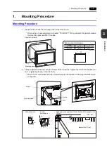
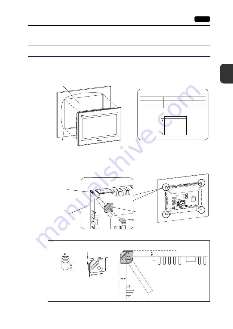
1. Insert the TS unit into the mounting panel (max. thick: 5 mm).
* When using an optional waterproof gasket “TS1xx0-WP”, firmly sandwich the gasket between
the mounting panel and the TS series.
2. Fit the supplied four fixtures onto the screws of the TS series. Tighten them with the supplied four
nuts. (Tightening torque: 0.3 to 0.4 N•m)
* When the TS unit is attached to the mounting panel, the fixtures and frame grounds (FG) are
connected.
X
Y
TS1100
TS1070
X
Y
257.0
+0.5
-0
189.0
+0.5
-0
X
199.0
+0.5
-0
134.0
+0.5
-0
Y
Model
Panel cut-out dimensions
Unit: mm
Panel cut-out hole
Mounting panel
4.2
8.5
8.5
17.5
17.5
8
14.0
• Fixture
dimensions
Fixture
Nut
Screw
• Dimensions of a tightened fixture that lies off the edges of the
TS unit
Back of the TS unit
Mounting panel
(
Unit: mm)
• Nut dimensions
Summary of Contents for MONITOUCH TS Series
Page 1: ......
Page 10: ...11 Features 2 Models and Peripheral Equipment 3 System Composition Product Outline ...
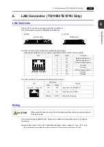
Page 43: ...2 26 6 LAN Connector TS1100i TS1070i Only Please use this page freely ...
Page 44: ...31 Mounting Procedure 2 Power Supply Cable Connection Installation ...
Page 49: ...41 Coin type Lithium Battery 2 DIP Switches Handling of TS Series Components ...
Page 57: ...4 8 2 DIP Switches Please use this page freely ...
Page 58: ...51 Before Operation 2 Main Menu Screen 3 System Menu TS Series Operations ...
Page 102: ...5 44 3 System Menu Please use this page freely ...
Page 103: ...61 Error Messages 2 Troubleshooting Error Handling ...
Page 110: ...71 Inspection and Maintenance 2 Warranty Policy Inspection and Maintenance ...
Page 114: ...7 4 2 Warranty Policy Please use this page freely ...


