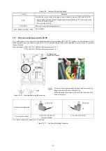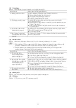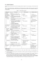
[ 2 ] Terminal functions (main circuit terminals)
Classifi-
cation
Symbol Name
Functions
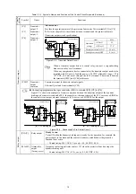
DB1, DB2, DB3
External braking
resistor connecting
terminal
Three sets of external braking resistor are used, and it connects with DB1, DB2, and
DB3 between DC link bus N bars.
P(+), N(-)
Inverter P(+)-N(-)
line connecting
terminal
Connects the P(+)-N(-) line of inverter.
R0, T0
Auxiliary power
inputs for control
circuit
Connect the same AC power lines as the main power input for a backup of the control
circuit power supply.
When the inverter is used in combination with the PWM converter, insert an insulation
transformer or auxiliary B contact (normally-closed) of a power side magnetic
contactor.
R1, T1
Auxiliary power
inputs for fans
Power terminals for AC cooling fans. Connect an AC power supply to these terminals.
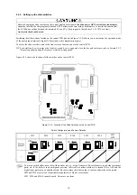
To match the power specifications, set the fan power switching connectors U1 and U2.
For details, refer to Section 2.2.7.
DCF1, DCF2
Inputs for fuse
blowout detection
Terminals for detecting a blowout of the DC fuse.
When the circuit between terminals [DCF1] and [DCF2] is OFF, the dynamic breaking
unit can detect the blowout of the DC fuse.
To use the detection function, remove the short bar from these terminals to close the
microswitch of the DC fuse. (24 VDC 12 mA typ.)
Main circuit
G
Grounding for
dynamic breaking
unit
Grounding terminals of the dynamic breaking unit.
2.2.5 Control circuit terminals
[ 1 ] Screw specifications and recommended wire sizes
(control circuit terminals)
Table 2.2-3 lists the screw specifications and recommended wire size for wiring of the control circuit terminals.
Table 2.2-3 Screw Specifications and Recommended Wire Size
Screw specifications
Recommended wire size (mm
2
)
Screw size
Tightening torque (N·m)
Control circuit terminals
M3
0.7
1.25 *
[ 2 ] Terminal arrangement (control circuit terminals)
Not available terminal. Don’t connect any wire.
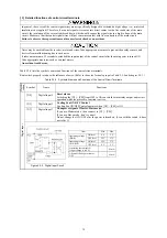
Do not remove the short bar of [EN1], [EN2] and [PS] terminal.
12
Summary of Contents for BUC S-69D
Page 8: ......


