Leaders in environmentally friendly wastewater management
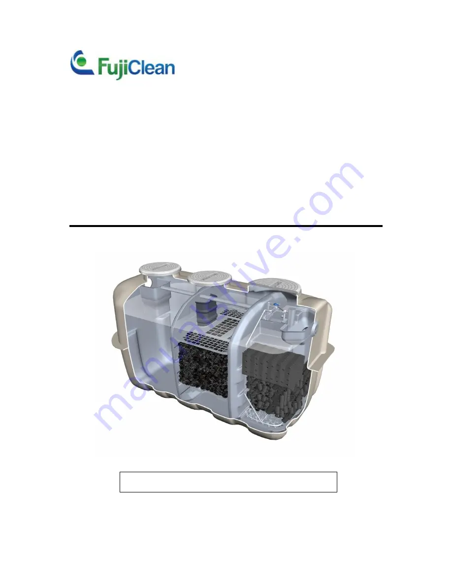
COMMERCIAL
WASTEWATER
TREATMENT
SYSTEM
CE-4200
CE-6000
Operation & Maintenance Manual
FOR SERVICE PERSONNEL ONLY
Updated: 19 January 2015
Page 1: ...Leaders in environmentally friendly wastewater management COMMERCIAL WASTEWATER TREATMENT SYSTEM CE 4200 CE 6000 Operation Maintenance Manual FOR SERVICE PERSONNEL ONLY Updated 19 January 2015 ...
Page 2: ... and according to local regulations Read the chemical label before opening the package Understand the directions for use and safety information before starting an application Working in confined spaces Personnel required to enter and carry out maintenance work in the unit must comply with confined space regulations Electrical safety Do not touch any components in the blower box with wet hands Read...
Page 3: ...ilter media lower section In the upper section the board contact media adjusts inflow from the anaerobic filtration chamber and organic matters are decomposed by micro organism bacteria on the contact media surface Also organic matters are decomposed by micro organism bacteria on the filter media surface while suspended solids are captured in the lower section Suspended solids accumulated on the b...
Page 4: ... can effectively cope with shock loading The system has a buffer capacity of 252L for CE4200 and 301L for CE6000 The water level in the system varies whether there is any inflow or not When the water level exceeds the Low Water Level LWL the treated water is pumped out to the pump chamber through the chlorinator by the effluent airlift pump If the water level exceeds the High Water Level HWL the t...
Page 5: ...if necessary Turn off the blower for a few moments to check that the alarm is triggered 4 Open all access covers and secure the area around the access openings 5 Collect a sample of treated effluent from the pump chamber and check the condition 6 Check if the high water float switch and the pump float switch are operating freely Lift up the pump float switch to check that the pump operates properl...
Page 6: ...rculation rate accordingly Otherwise use the table below to set the recirculating rate CE4200 CE6000 Recirculation Rate L minute 6 0 12 8 17 Valve Reading 30 35 15 20 Important Too much recirculation can cause stirring or agitation in the sedimentation chamber and solids to flow into the anaerobic chamber Also treatment performance could be deteriorated and this could cause odour 3 Measuring Recir...
Page 7: ...ve grey valve to the original position Step 4 Aerate one side of the chamber by turning the Aeration Balance Control Valve blue valve fully one way Wait for one minute and then turn the valve fully to the opposite direction Wait for another minute and then reset the valve to the original position Step 5 Repeat Step 2 4 a few times Step 6 Perform Step 2 Step 7 Reset the Recirculation Control Valve ...
Page 8: ...rcial System Step 5 Reconnect the aeration pipework Step 6 Turn on the blower and adjust all the valve settings Servicing the Effluent Air lift Pump The Effluent Air lift Pump can be checked even while the water level is at the Low Water Level LWL Push down the air lift pump so that the water flows into the inflow opening or pour water directly into the air lift pump and see if the water is discha...
Page 9: ...ly by using PVC or stainless steel pipe with less than 20mm outside diameter Nitrogen gas trapped in the media will be released during this process 2 Backwashing Anaerobic Media If the anaerobic media is blocked connect pipe with a blower to backwash the media as shown below The end of the pipe should be above the bottom of the media so that the accumulated sludge at the bottom of the tank is not ...
Page 10: ...c filtration chamber builds up to reach the bottom of the filtration media and the sludge flows into the next chamber Excessive suspended solids are observed in the aerobic contact filtration chamber and the symptoms do not improve even after performing a sludge transfer Desludging Procedures Step 1 Turn off all electrical components Step 2 Clean the inlet and outlet pipe Step 3 Transfer suspended...
Page 11: ...ove scum and sludge in the sedimentation chamber Step 7 optional Although it is unnecessary to vacuum the aerobic contact filtration chamber it is possible to do so by inserting the suction hose into the storage chamber and sucking water from the bottom while washing the media and chamber wall with high pressure water Step 8 Fill the plant with water to LWL Step 9 Turn on all electrical components...
Page 12: ...tering the system Remind the homeowner to refrain from disposing prohibited substances and limited use substances Anaerobic Filtration Chamber Symptom Solution Excessive scum accumulations less than 100mm If the sedimentation chamber still has the remaining sludge holding capacity transfer the scum to the sedimentation chamber otherwise have the plant pumped out Excessive scum accumulations more t...
Page 13: ...em still persists backwash the filtration media by using a PVC pipe Storage Chamber Symptom Solution Scum forming Transfer the scum to the sedimentation chamber Excessive sludge accumulations Transfer the sludge to the sedimentation chamber Ph is too low or too high Ph 5 8 or Ph 8 6 Check to make sure the recirculation rate is appropriate Remind the homeowner not to dispose any prohibited substanc...
Page 14: ...k to make sure the circuit breaker has not tripped Send the blower to authorised service personnel Air pressure is too low Rectify air leaks Abnormal noise or vibration Ensure the blower is not touching the wall Ensure the mounting legs of the blower firmly contact the base Dirty or clogged air filter Clean or replace the filter In the event that the system requires repair or the components need t...
Page 15: ... Nominal Size dia 125 CE6000 Volume L Dimensions mm Sedimentation Chamber 4 520 Max Width 1 990 Anaerobic Filtration Chamber 4 511 Max Length 4 665 Aerobic Contact Filtration Chamber 2 006 Max Height No riser 2 215 Storage Chamber 1 009 Max Height with 300mmH risers 2 515 Pump Chamber 64 Inlet Invert No riser 400 Total Volume 12 110 Inlet Invert with 300mmH risers 700 Weight kg 700 Inlet Pipe Nomi...
Page 16: ...ch as moisture and bad connections can cause erratic behaviour It is also advised to avoid joins in the cable NB lf the 2 wire alarm cable is to be run in the same conduit as the mains supply to this unit from the house the alarm cable must be 240VAC rated Caution needs to be exercised when connecting this alarm wiring as inadvertent connection to the mains voltage will irreversibly damage both th...