


Maxi-Cool
Installation and Startup
Rev 007, 04/12
5
© SP Scientific 2012
Electrical Requirements
The voltage and frequency requirements are specified on the serial tag on the rear of
the unit. Standard variances in frequency (+/-3Hz) and voltage (-5%, +10%) are
allowed.
CAUTION! IF YOU ARE UNSURE ABOUT THE AVAILABLE ELECTRICAL VOLTAGE SUPPLY IN
YOUR FACILITY, CONSULT A QUALIFIED ELECTRICIAN.
Verify that the facilities voltage matches the requirement for the machine,
1.
which is printed on the serial tag on the rear of the machine.
The electric service wiring must be of a large enough wire gauge that the
2.
voltage is maintained to the receptacle even when a full load is applied to the
receptacle. Additionally, the receptacle voltage should be measured while that
receptacle is under load.
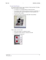
This unit has a NEMA 5-15P or 6-15P line cord, install an appropriate (NEMA
3.
5-15R or 6-15R) receptacle where the unit is to be run (some 50 Hz machines
are shipped with no plug).
Ensure the proper amperage circuit breaker is installed in the line and located
4.
near the equipment.
Ensure the POWER switch on the front panel of the machine is in the EMO
5.
position (0).
Plug in the line cord. Avoid the use of long extension cords, these cause a
6.
significant power drop between the wall receptacle and the machine.
Check for power at the unit by moving the POWER switch to the ON (I)
7.
position, the amber POWER light on the front panel should illuminate
Note:
For Lock Out / Tag Out plug the appropriate device into the line cord.
Summary of Contents for MAXI-COOL
Page 1: ...RECIRCULATING CHILLER OPERATOR S MANUAL MAXI COOL with EDC Control ...
Page 2: ......
Page 6: ...iv Rev 007 04 12 SP Scientific 2012 ...
Page 10: ...Introduction Maxi Cool 2 Rev 007 04 12 SP Scientific 2012 ...
Page 19: ...Maxi Cool Installation and Startup Rev 007 04 12 11 SP Scientific 2012 ...
Page 26: ...Operation Maxi Cool 18 Rev 007 04 12 SP Scientific 2012 ...
Page 36: ...User Menu Maxi Cool 28 Rev 007 04 12 SP Scientific 2012 ...
Page 65: ......