Section 4 Service, Configuration & Testing
21
FT742-SM (RS422 & RS485) Sensors
– User Manual
Acu-Vis software will run on Window XP, Vista, Windows 7, 8 and 10 PC computers
Warning: Live connection/disconnection of the power and/or sensors during live operation, or mis-wiring
of the power leads
could damage the equipment and is not covered by FT’s standard warranty terms
Acu-
Vis will not work if the sensor is running in ‘Continuous Update’ mode due to the continuous use of
the communication channels. It will be necessary to disable CU mode (and potentially re-enable it
following testing) if Acu-Vis is required for use
5.4 Software Installation
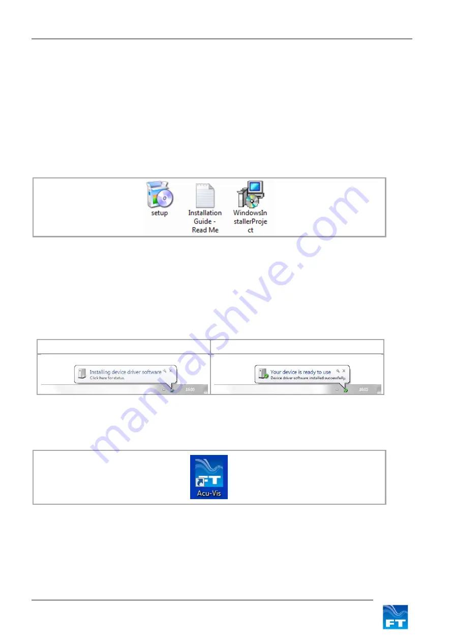
1. Insert the Acu-Vis CD in to the PC and install Acu-Vis, by running the setup.exe file (Windows
administrator privileges may be required to install software).
Figure 10: Acu-Vis Install Files
2. Remove the FT742-SM sensor and USB test cable from their packaging and mate the connectors
together
3. Connect the +24 VDC terminal of the power supply (current limit up to 2.5A) to the white wire (Red test
plug) and 0V terminal to the brown wire (black test plug). Then switch on the power supply.
4. Connect the USB cable to the Computer and allow Windows to detect the cable and install any drivers.
Please wait for Windows to install the hardware
Ready for use
Figure 11: Windows driver installation sequence
5. Once the above sequence is complete, wait approximately 10 seconds and then run Acu-Vis by
selecting the shortcut icon on the desktop or from the start menu in the FT Technologies folder.
Figure 12: Acu-Vis Shortcut Icon
6. If you need to change over the evaluation cable it is recommended to firstly close the program, replace the
cable and allow enough time for Windows to recognise the new cable and install its drivers. Then restart
Acu-Vis.
In case of installation difficulties contact your IT administrators who may be able to assist with installation
permissions.


