Frontier SKYTRAQ VENUS 838 Manual Download Page 5

Low cost receiver 

Prototype 


pg. 5 


Low-Cost SBAS Receiver Design (SkyTraq Venus 838) - 25/02/2020 

This document describes Open Hardware and is licensed under the CERN OHL v. 1.2.


You may redistribute and modify this documentation under the terms of the CERN OHL v. 1.2. (

http://ohwr.org/cernohl

) 

This documentation is distributed WITHOUT ANY EXPRESS OR IMPLIED WARRANTY, INCLUDING MERCHANTABILITY, SATISFACTORY QUALITY AND 

FITNESS FOR A PARTICULAR PURPOSE. Please see the CERN OHL v. 1.2 for applicable conditions 

3.3.2.


HC-06 Connection 

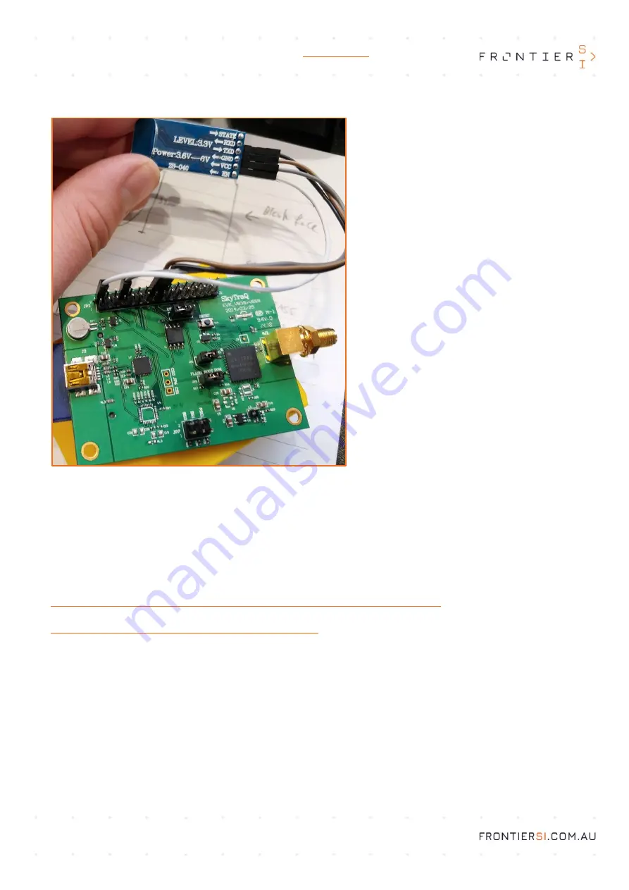
The SkyTraq Evaluation board can now be 
connected to the HC-06 Bluetooth module via the 
header pins. As you can see in the diagram to the 
left, there are 4 jumper wires connecting these two 
components.  
The components should be connected as follows: 


SkyTraq Pin 2 -> HC-06 VCC 


SkyTraq Pin 8 -> HC-06 GND 


SkyTraq Pin 16 (RX) -> HC-06 TXD 


SkyTraq Pin 18 (TX) -> HC-06 RXD 

Try and ensure that these connections are stable 
and will not pull themselves free under vibrations 
from regular use. 
You should now be able to plug the USB A from the 
Adafruit PowerBoost 1000 into the MiniUSB on the 
SkyTraq Venus 838 board. Toggling the switch 
should cause the LEDs on the SkyTraq to illuminate. 
The next step is to allow the SkyTraq and HC-06 to 
communicate. 


3.4.


Configuring the SkyTraq output baudrate 

The HC-06 Bluetooth module comes with a default baudrate of 9600. To function correctly, both the HC-06 and the SkyTraq 
must be set to the same baudrate. It is a much simpler task to alter the baudrate of the SkyTraq than the HC-06, so that is 
the recommended method.  

To alter the SkyTraq baudrate, you will need to download some drivers and an application to a PC.  

You can find the USB drivers here: 

https://www.silabs.com/products/development-tools/software/usb-to-uart-bridge-vcp-drivers


And you can find the configuration software / data viewer here: 

http://navspark.mybigcommerce.com/content/GNSS_Viewer.zip


Once you have installed both of these, it is advisable to restart your PC.  
Once restarted, try connecting the SkyTraq directly via USB to the PC, with the HC-06 module RX and TX disconnected from 
the SkyTraq header pins. Having these pins connected can cause issues when attempting to interface with the board until 
the baudrates are matched. You should see the SkyTraq appear in the ports (COM & LPT) section of Device Manager. Note 
the COM port number that this is connected to. If you are unsure about which device is the SkyTraq, try disconnecting and 
reconnecting the device, and note which device appears in Device Manager.  

Once you have opened GNSS Viewer, you will find a section in the Top-Left corner with a drop-down list for COM ports, and 
a drop-down for baudrate next to it. If you are unsure about either of these values, the software has a feature to Scan Port 
or Scan Baud, which will iterate through until it finds the correct port and baudrate. If you know the COM port number, enter 

that here, and press the “Close” button to open the connection. If this has connected p

roperly, you will see some data in the 

“Message” and “Response” sections of GNSS Viewer. Now navigate to the “Binary” drop

-

down menu and select “Configure 

Summary of Contents for SKYTRAQ VENUS 838

Page 1: ...or applicable conditions LOW COST SBAS RECEIVER DESIGN SKYTRAQ VENUS 838 Table of Contents 1 COMPONENTS 2 2 REQUIRED EQUIPMENT 2 3 BUILD PROCEDURE 2 3 1 3D Printing the Enclosure 2 3 1 1 Main Enclosure 2 3 1 2 Enclosure Lid 3 3 1 3 Charger Tray 3 3 2 Preparing the Components 3 3 2 1 Attaching Headers to the SkyTraq Venus 838 Evaluation Board 3 3 2 2 Preparing the Adafruit PowerBoost 1000 4 3 3 Ass...

Page 2: ...ms no affiliation with the creators and distributors of any of these components These were selected for their availability and relatively low cost Alterations on this design may function with alternative components but the enclosures have been dimensioned with these in mind 2 Required Equipment You will require the following equipment and the skills necessary for their safe operation 3D Printer So...

Page 3: ...bels to print correctly 3 1 3 Charger Tray This tray is dimensioned to fit the Adafruit PowerBoost 1000 Charger Board Once assembled both this tray and the board will hang upside down from the rail in the Main Enclosure with the USB port exposed externally to allow easy recharging Depending on your 3D printer and settings this will take less than 1 hour to produce 3 2 Preparing the Components 3 2 ...

Page 4: ...ections necessary to construct the assembly shown in the image to the left The toggle switch should be connected to the header pins labelled EN and GND From there the 2400 mAh LiPo can be connected using the attached plug If this assembly is working correctly the switch should turn the board on and off which will be visible via the power and charge level lights on the PowerBoost 1000 When the swit...

Page 5: ...uch simpler task to alter the baudrate of the SkyTraq than the HC 06 so that is the recommended method To alter the SkyTraq baudrate you will need to download some drivers and an application to a PC You can find the USB drivers here https www silabs com products development tools software usb to uart bridge vcp drivers And you can find the configuration software data viewer here http navspark mybi...

Page 6: ...eft you should enable the SBAS system disable Ranging enable the corrections and then enable WAAS From there use the Modify Default PRN section to change the WAAS PRN to 122 the PRN of the Australia and New Zealand SBAS You can now save the configuration It is also recommended to disable position pinning to allow true 1hz or higher output rates and to change the Navigation mode to suit your use ca...

Page 7: ...the front edge of the SkyTraq board with HC 06 attached you can leave it dangling out for now into the opening of the bottom rails so that it s lined up square ready to be pushed in 3 Push the SkyTraq board in far enough that the Antenna connector is past the opening to the power assembly rail 4 Place the battery slightly into the compartment leaving slack in the wires to line up the SkyTraq board...

Page 8: ...ve in built support for bluetooth GNSS receivers however some may require the use of a Mock Location sourced from an app that can take a bluetooth receiver input to function properly 5 Troubleshooting The most common issue when constructing this receiver is mis configured baudrate between the HC 06 and the SkyTraq board If they do not match the communications will not work as expected in either di...

Reviews: