Fronius GEN24 inverter
General
IMPORTANT!
Settings in the "Device configuration" menu item may only be
entered by staff trained to do so!
The service password must be entered for the "Device configuration" menu item.
Three-phase or one-phase Fronius Smart Meters may be used. In both cases, se-
lection is made via the "Components" menu area. The meter type is determined
automatically.
One primary meter and several secondary meters can be selected. The primary
meter must be configured before a secondary meter can be chosen.
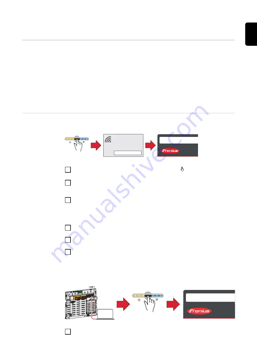
Installation with
the browser
WLAN:
open access point
1
FRONIUS_PILOTxxx
Secured
Password:
12345678
2
192.168.250.181
1
Open the access point by touching the sensor once → Communications
LED: flashes blue.
2
Establish the connection to the inverter in the network settings (the inverter
is displayed with the name "FRONIUS_PILOT" and the serial number of the
device).
3
Enter password: 12345678 and confirm.
IMPORTANT!
To enter the password in Windows 10, first select the "Connect using a secur-
ity key instead" link to be able to establish the connection with the password:
12345678.
4
Enter the IP address 192.168.250.181 in the address bar of the browser and
confirm. The installation wizard opens.
5
Follow the installation wizard and complete the installation in the individual
areas.
6
Add the system components in Solar.web and commission the PV system.
The network wizard and product setup can be performed independently. A net-
work connection is required for the Solar.web installation wizard.
Ethernet:
169.254.0.180
2
1
open access point
1
Establish a connection to the inverter (LAN1) using a network cable (min.
CAT5 STP).
27
EN-US
Summary of Contents for WND-WR-MB
Page 2: ......
Page 17: ...17 EN US ...
Page 23: ...Commissioning 23 ...
Page 24: ...24 ...
Page 29: ...The Fronius Smart Meter is configured as a secondary meter 29 EN US ...
Page 35: ...35 EN US ...
Page 36: ... ...


