


Starting Up the Welding Torch Service Station
General
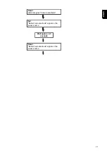
NOTE!
If wetting agent has not been applied to the inside of the welding torch, this may
lead to the permanent contamination of the welding torch when welding begins.
Always wet the inside of the welding torch with the manufacturer's "Robacta Reamer"
parting agent before starting an automatic application.
To achieve optimum cleaning results, observe the following points:
-
Always wet the inside of the welding torch with parting agent
-
Adhere to the specified cleaning procedures
-
Adhere to the specified cleaning positions
Opening the
Welding Torch
Service Station
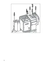
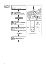
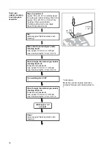
If the welding torch service station is equipped with an optional fieldbus as a robot con-
trol unit connection, the service station for connecting the robot control unit and for fault
diagnosis of the fieldbus must be opened as follows:
*
4
3
2
1
3
3
2
2
1
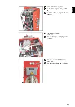
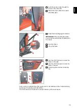
Remove collecting tray
2
Remove three TX25 screws on the left
3
Remove three TX25 screws on the
right
4
Remove frame
* Position of the bus coupler
Requirements for
Starting Up
The following requirements must be met in order to commission the cleaning device:
-
Securely bolt the welding torch service station to the surface
-
Any available optional equipment installed on the welding torch service station, sup-
plied with compressed air and connected to the grid if necessary
-
Compressed air supply to the welding torch service station established
-
Cleaning device connected to the robot control unit
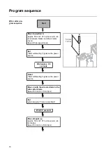
Starting Up the
Welding Torch
Service Station
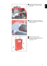
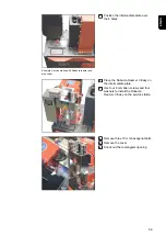
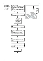
1
Check whether all optional equipment is correctly connected to the welding torch
service station
2
Connect welding torch service station to the robot control unit
max. length of the control cable = 30 m
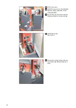
3
Establish electrical supply to the optional equipment
max. length of the mains cable = 30 m
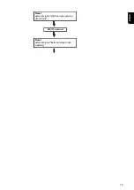
4
Establish compressed air supply
max. length of the compressed air supply line = 30 m
62
Summary of Contents for Robacta TSS /i
Page 2: ......
Page 11: ...General 11 ...
Page 12: ...12 ...
Page 18: ...18 ...
Page 19: ...Operating controls connections and mechanical components 19 ...
Page 20: ...20 ...
Page 32: ...32 ...
Page 33: ...Installation and Startup 33 ...
Page 34: ...34 ...
Page 61: ...12 12 12 Connect the compressed air supply 61 EN US ...
Page 64: ...64 ...
Page 65: ...Cleaning Program Sequence 65 ...
Page 66: ...66 ...
Page 68: ...A B C D E F G 68 ...
Page 79: ...Reset external signal Internal valve brush cleaning 79 EN US ...
Page 84: ...Reset external signal Cut wire electrode End of the cleaning process Welding 84 ...
Page 85: ...Troubleshooting Maintenance and Disposal 85 ...
Page 86: ...86 ...
Page 97: ...Appendix 97 ...
Page 98: ...98 ...