


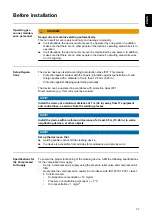


Before installation
Operating per-
sonnel, mainten-
ance personnel
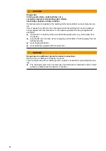
WARNING!
Danger due to machines starting automatically.
This can result in severe personal injury and damage to property.
▶
In all situations, the device must only ever be operated by one person. In addition,
make sure that there are no other people in the device's operating area while it is in
operation.
▶
In all situations, the device must only ever be maintained by one person. In addition,
make sure that there are no other people in the device's operating area while work
on it is ongoing.
Setup Regula-
tions
The device has been tested according to protection class IP21. This means:
-
Protection against contact with the fingers, protection against penetration of solid
foreign bodies with a diameter of more than 12.5 mm (0.49 in.)
-
Protection against dripping water falling vertically
The device can be operated in accordance with protection class IP21.
Direct moisture (e.g. from rain) must be avoided.
NOTE!
Install the device at a minimum distance of 1 m (40 in.) away from IT equipment
and control lines, as well as from the welding process.
NOTE!
Install the device with an all-round clearance of at least 0.5 m (19.69 in.) to walls,
neighboring devices, or other objects.
NOTE!
Set up the device so that
▶
welding spatter cannot hit the cleaning device,
▶
the device is accessible from all sides for maintenance and service work.
Specifications for
the Compressed
Air Supply
To ensure the proper functioning of the cleaning device, fulfill the following specifications
for the compressed air supply:
-
Set up a compressed air supply using the pressure relief valve and compressed air
filter
-
Guarantee the compressed air quality in accordance with ISO 8573-1:2001, class 7
4 3, instrument air
•
Solid particle concentration
£
10 mg/m
3
•
Pressure concentration point vapor
£
+ 3°C
•
Oil concentration
£
1 mg/m
3
37
EN-US
Summary of Contents for Robacta TSS /i
Page 2: ......
Page 11: ...General 11 ...
Page 12: ...12 ...
Page 18: ...18 ...
Page 19: ...Operating controls connections and mechanical components 19 ...
Page 20: ...20 ...
Page 32: ...32 ...
Page 33: ...Installation and Startup 33 ...
Page 34: ...34 ...
Page 61: ...12 12 12 Connect the compressed air supply 61 EN US ...
Page 64: ...64 ...
Page 65: ...Cleaning Program Sequence 65 ...
Page 66: ...66 ...
Page 68: ...A B C D E F G 68 ...
Page 79: ...Reset external signal Internal valve brush cleaning 79 EN US ...
Page 84: ...Reset external signal Cut wire electrode End of the cleaning process Welding 84 ...
Page 85: ...Troubleshooting Maintenance and Disposal 85 ...
Page 86: ...86 ...
Page 97: ...Appendix 97 ...
Page 98: ...98 ...