


3
Open the access point by touching the sensor once → Communication LED:
flashes blue.
4
Follow and complete the installation wizard in the individual sections.
5
Add system components in Solar.web and start up the PV system.
The network wizard and the product setup can be carried out independently of
each other. A network connection is required for the Solar.web installation wiz-
ard.
Installation us-
ing the web
browser
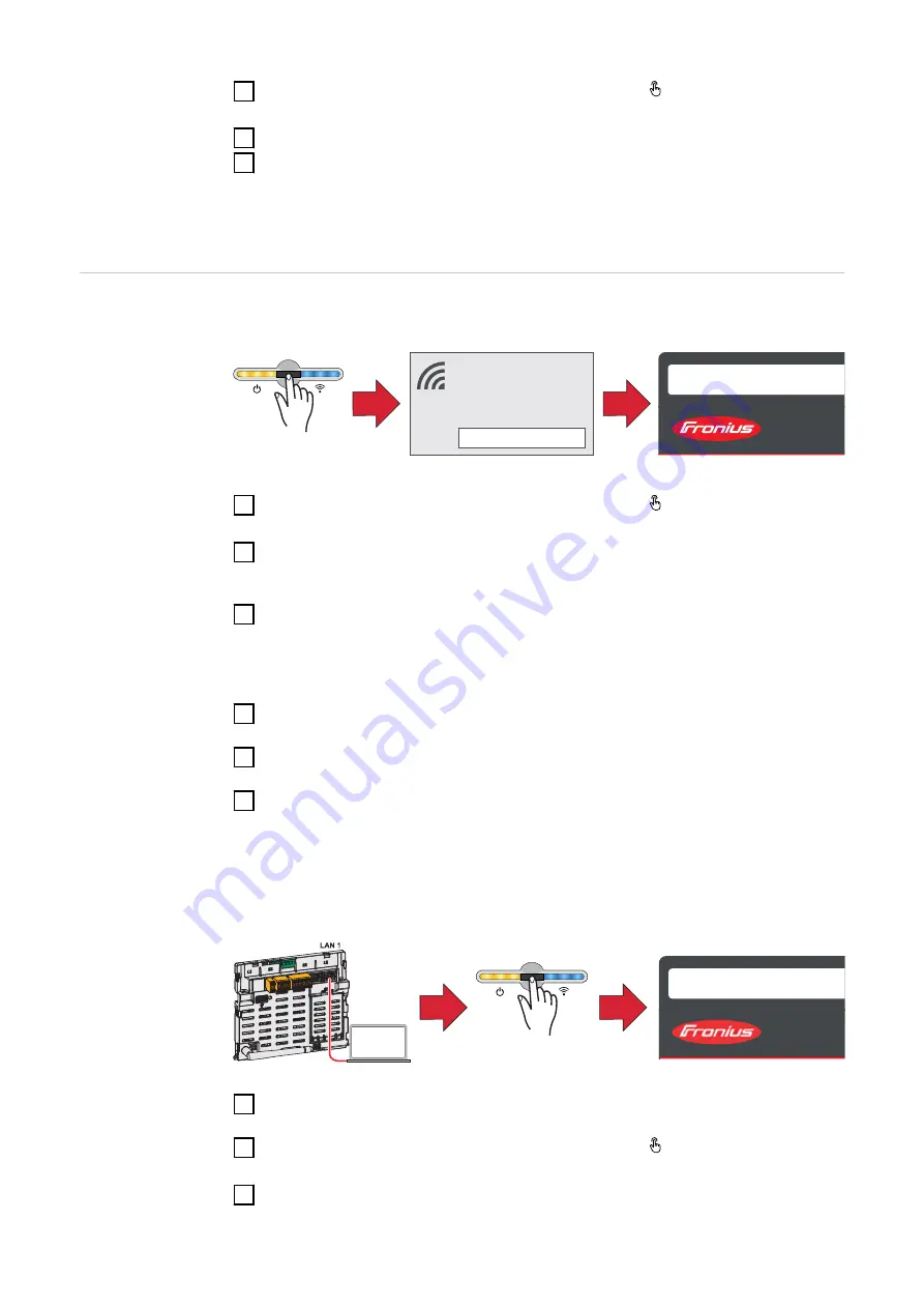
WLAN:
open access point
1
FRONIUS_PILOTxxx
Secured
Password:
12345678
2
192.168.250.181
1
Open the access point by touching the sensor once → Communication LED:
flashes blue.
2
Establish the connection to the inverter in the network settings (the inverter
is displayed with the name "FRONIUS_PILOT" and the serial number of the
device).
3
Password: enter 12345678 and confirm.
IMPORTANT!
To enter the password on a Windows 10 operating system, the link "Connect
using a security key instead" must first be activated to establish a connection
with the password: 12345678.
4
In the browser address bar, enter and confirm the IP address
192.168.250.181. The installation wizard is opened.
5
Follow the installation wizard in the individual sections and complete the in-
stallation.
6
Add system components in Solar.web and start up the PV system.
The network wizard and the product setup can be carried out independently of
each other. A network connection is required for the Solar.web installation wiz-
ard.
Ethernet:
169.254.0.180
2
1
open access point
1
Establish a connection to the inverter (LAN1) with a network cable (CAT5
STP or higher).
2
Open the access point by touching the sensor once → Communication LED:
flashes blue.
3
In the browser address bar, enter and confirm IP address 169.254.0.180. The
installation wizard is opened.
98
Summary of Contents for Primo GEN24 3.0
Page 2: ......
Page 12: ...12...
Page 13: ...General information 13...
Page 14: ...14...
Page 34: ...34...
Page 35: ...Backup power variant PV Point OP 35...
Page 36: ...36...
Page 38: ...38...
Page 39: ...Backup power variant Full Backup 39...
Page 40: ...40...
Page 48: ...48...
Page 49: ...Installation 49...
Page 50: ...50...
Page 57: ...Do not install the inverter on the ceiling 57 EN...
Page 101: ...Settings user interface of the in verter 101...
Page 102: ...102...
Page 132: ...132...
Page 133: ...Options 133...
Page 134: ...134...
Page 144: ...144...
Page 145: ...Appendix 145...
Page 146: ...146...
Page 172: ...172...
Page 173: ...Circuit diagrams 173...
Page 174: ...174...
Page 175: ...Circuit Diagram PV Point OP Circuit Diagram 175 EN...
Page 176: ...Fronius Primo GEN24 and BYD Battery Box Premium HV Circuit Diagram 176...
Page 179: ...Automatic switch to backup power 1 pin double separation e g Austria Circuit Diagram 179 EN...
Page 180: ...Automatic switch to backup power 1 pin single separation e g Australia Circuit Diagram 180...
Page 181: ...Automatic switch to backup power 2 pin double separation e g Germany Circuit Diagram 181 EN...
Page 182: ...Automatic switch to backup power 2 pin single separation e g France Spain Circuit Diagram 182...
Page 183: ...Automatic switch to backup power 2 pin double separation e g UK Circuit Diagram 183 EN...
Page 185: ...Fronius Primo GEN24 with Enwitec Box Circuit Diagram 185 EN...
Page 186: ...Wiring diagram surge protective device SPD Circuit Diagram 186...
Page 187: ...Dimensions of the inverter 187...
Page 188: ...188...
Page 189: ...Fronius Primo GEN24 3 6 kW Fronius Primo GEN24 3 6 kW 189 EN...
Page 190: ...190...
Page 191: ...191 EN...
Page 192: ......


