background image

3

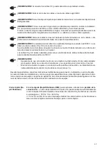
IMPORTANT SAFETY INSTRUCTIONS - SAVE THE

-

SE INSTRUCTIONS

General

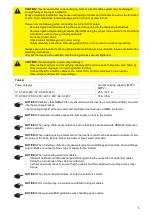
This manual contains important instructions for the inverter that must be followed during 

installation and maintenance of the inverter.

The inverter is designed and tested according to international safety requirements. Due to 

its electrical and electronic components, certain precautions must be taken when installing 

and operating the inverter.

In order to reduce the risk of injury to persons and to ensure safe installation and operation 

of the inverter, be sure to read these Operating Instructions carefully and follow all instruc

-

tions and safety instructions.

Failure to observe the Operating Instructions and safety instructions can void the warranty 

and/or cause damage to the inverters or other property damage!

Safety

The following section "Safety“ contains various warnings. A Warning describes a hazard 

to equipment or personnel. It calls attention to a procedure or practice, which, if not cor

-

rectly performed or adhered to, could result in damage to or destruction of part or all of the 

Fronius inverter and/or other equipment connected to the Fronius inverter or personal in

-

jury.

Electrical installa

-

tions

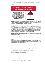
All electrical installations must be carried out in accordance with the National Electrical 

Code, ANSI/NFPA 70, and any other codes and regulations applicable to the installation 

site.

For installations in Canada, the installations must be done in accordance with applicable 

Canadian standards.

Summary of Contents for 10.0-3 208

Page 1: ...fect Charging Perfect Welding Solar Energy 42 0410 0249 023 29092020 Fronius Symo Advanced Installation 10 0 3 208 240 15 0 3 480 20 0 3 480 22 7 3 480 24 0 3 480 Installation Instruction Inverter for...

Page 2: ...2...

Page 3: ...re to observe the Operating Instructions and safety instructions can void the warranty and or cause damage to the inverters or other property damage Safety The following section Safety contains variou...

Page 4: ...ance with applicable Canadian standards Use min 194 F 90 C copper wire for all grounding wires see NEC table 250 122 For all AC DC wires use a minimum of 167 F 75 C Voltage drop and other consideratio...

Page 5: ...nals on the inverter Observe the maximum DC input voltage Table A Power category Current carrying capacity MPP1 MPP2 10 0 3 208 240 12 0 3 208 240 25 A 16 5 A 15 0 3 480 20 0 3 480 22 7 3 480 24 0 3 4...

Page 6: ...uit supplied with the inverter In this case AC and DC cables must only be laid together when the cable insulation is designed for the maximum possible voltage of 1000 V for both cables NOTICE Make sur...

Page 7: ...unting of the inverter on PV modules Self test A self test of the RSD function can be performed manually or automatically The self test only affects the discharge circuit of the RSD function All other...

Page 8: ...fonctionnement s curis s de l onduleur Le non respect des instructions de service et des consignes de s curit peut entra ner l an nulation de la garantie et ou des dommages aux onduleurs ou d autres...

Page 9: ...tives en vigueur sur le site de l installation Les installations au Canada doivent tre r alis es conform ment aux normes canadiennes en vi gueur Utiliser des fils en cuivre minimum 90 C 194 F pour tou...

Page 10: ...les vis de fixation ATTENTION Risque de dommages sur l onduleur en raison d une surcharge Respecter l intensit maximale admissible des diff rentes classes de puissance voir tableau A Raccorder au maxi...

Page 11: ...r s la d tection d un arc lectrique contr ler l tat de l ensemble de l installation photovolta que concern e REMARQUE Si l isolation du c ble AC n est pas con ue pour un maximum de 1 000 V les c bles...

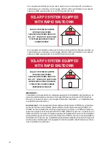
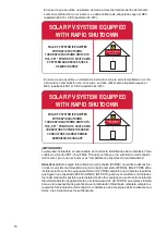
Page 12: ...l te r pond aux exigences fonctionnelles d arr t rapide Cet quipement doit tre install conform ment aux instruc tions d installation du fabricant Si un quipement d arr t au niveau des modules au sein...

Page 13: ...configur s de fa on particuli rement s re afin d viter les erreurs D roulement de l autocontr le automatique chaque d marrage avant la connexion au r seau public le circuit de d charge est ac tiv pen...

Page 14: ...es y seguir todas las instrucciones e indicaciones de seguridad El incumplimiento de este manual de instrucciones y de las instrucciones de seguridad puede dar lugar a la anulaci n de la garant a y o...

Page 15: ...as vigentes para el lugar de instalaci n Las instalaciones en Canad deben realizarse seg n las normas canadienses vigentes Para todos los cables de puesta a tierra deben utilizarse hilos de cobre con...

Page 16: ...uenta la m xima intensidad de corriente admisible de los diferentes rangos de potencia ver la tabla A Conectar como m ximo 33 A a un solo borne de conexi n CC Conectar los cables CC y CC con la polari...

Page 17: ...sor despu s de haber detectado un arco voltaico com probar toda la instalaci n fotovoltaica afectada con respecto a posibles da os OBSERVACI N Si el aislamiento del cable CA no est dise ado para un m...

Page 18: ...ltaica completa cumpla los requisitos funcionales de cierre r pido La instalaci n de este equipo debe realizarse con forme a las instrucciones de su fabricante En caso de que se utilice un sistema de...

Page 19: ...mutaci n RSD est n fabricados a prueba de fallos Proceso de Autotest autom tico En cada proceso de inicio antes de la conexi n a la red p blica si se dispone de la sufi ciente tensi n CC 40 V se activ...

Page 20: ...onius Symo Installation Help English Fran ais Espa ol English www fronius com QR link 4204260202EA Fran ais www fronius com QR link 4204260202FR Espa ol www fronius com QR link 4204260202ES 1 2 3 SCAN...

Page 21: ...1154 ft 3400 m 10 0 3 12 0 3 208 240 UDC max 0 11154 ft 0 3400 m ft m 600 V 1000 V 0 6561 ft 0 2000 m 8202 9842 ft 2500 3000 m 6561 8202 ft 2000 2500 m 9842 11154 ft 3000 3400 m 950 V 900 V 850 V UDC...

Page 22: ...22 4 in 100 mm 4 in 100 mm 8 in 200 mm 40 F 140 F 40 C 60 C 0 100 AC AC AC DC DC DC DATCOM DATCOM Installation example of several inverters...

Page 23: ...23 1 1 1 1 ON OFF Lock 1 2 3 lb 4...

Page 24: ...24 1 1 1 NO NEMA ENCLOSURE TYPE 1 2 Al St 0 2 0 3 in 6 8 mm 3...

Page 25: ...25 1 EN US mast pole pile FR m t pile barre ES m stil pilla barra EN US Mounting to a metal carrier FR Montage sur un support m tallique ES Montaje en un soporte de metal 1...

Page 26: ...e 1 2 in 3 4 in 1 in 1 1 4 in 1 2 in DATCOM 3 4 in 1 1 4 in AC DC METAL EMPOSSING Remove parts fallen into the connection area before hanging the inverter to the wall bracket METAL EMPOSSING Remove pa...

Page 27: ...27 1 2...

Page 28: ...V 50 Hz 208 240 V 208 V 480 V 440 V 50 Hz 415 V Microgrid 208 V Microgrid 50 Hz 208 240 V Microgrid 50 Hz 415 V Microgrid 480 V 480 V 480 V Appropriate Inverters Symo Advanced 10 0 3 208 240 12 0 3 2...

Page 29: ...DC disconnect DC terminal block PV frame ground L1 L2 L3 N Grounding terminal Grounding electrode terminal L1 N L2 L3 Main grounding system Lockable AC disconnect switch DC DC Ungrounded solar modules...

Page 30: ...according to the actual device output Do not combine copper and aluminum cables together in a single terminal AWG solid AWG stran ded AWG stranded solid AWG solid solid AWG stranded stranded 4 2 6 2...

Page 31: ...0 AWG 10 AWG 10 AWG 8 220 VAC AWG 10 AWG 10 AWG 10 AWG 8 240 VAC AWG 12 AWG 10 AWG 10 AWG 10 15 0 3 480 20 0 3 480 22 7 3 480 Copper Cu Aluminium Al 440 VAC AWG 14 AWG 12 AWG 10 AWG 10 AWG 8 AWG 8 480...

Page 32: ...32 1 1 0 6 in 15 mm AC PE PE PE 1 OFF 1 GND GND Torque Nm lbf in see printing near wire terminal 3 max 80 A AC RCD National Standards Type A YES I N 100 mA...

Page 33: ...t AWG 4 copper or aluminum with input combiner 2 6 21 mm 10 4 AWG Al Cu 5 5 Nm 48 6 lbf in option DC DC 42 0201 4479 42 0201 4479 42 0201 4480 42 0201 4480 10 0 3 12 0 3 208 240 max 41 5 A 15 0 3 20 0...

Page 34: ...0 3400 m 950 V 900 V 850 V UDC max ft m 15 0 3 24 0 3 480 5 DC 1 PV 1 PV 1 PV 2 DC 1 DC 2 DC 2 max 33 A to a single DC terminal 1 DC DC 1 1 DC DC 2 2 DC DC 2 1 2 3 4 5 6 3 1 2 3 1 2 Each Terminal Imax...

Page 35: ...35...

Page 36: ...t remove cover Each Terminal I Each Terminal Imax max 15 A 15 A Replacing fuses E N To avoid the risk of a fire only replace faulty fuses with new ones of the same rating FR Afin d viter les risques d...

Page 37: ...37 Installing Datamanager 2 0 1 1 1 1 1 1 2 1 3 TX20 10 6 lbf in 1 2 Nm 1 2 4 5...

Page 38: ...38 DATCOM Connection 1 1 1 1 1 2 3 4...

Page 39: ...39 1 1 1 5 22 lbf in 2 5 Nm 6 7...

Page 40: ...us les tubes utilis s avec un mat riau d tanch ification lasticit permanente tanch ifier chaque entr e et sortie de tubes tanch ifier les deux extr mit s des tubes ES OBSERVACI N La condensaci n dentr...

Page 41: ...41 Operation 1 1 4 3 in 1 ON OFF Lock 22 1 lbf in 2 5 Nm 2...

Page 42: ...42 1 1 1 1 3 4 5 6...

Page 43: ...L Mon Symo Advanced 208 240 MG1N Microgrid 240V with NL Mon MG1P Microgrid 240V without NL Mon MG2N Microgrid 220V without NL Mon MG3N Microgrid 208V without NL Mon MG3P Microgrid 208V without NL Mon...

Page 44: ...44 1 1 1 1 S E T U P A u t o D a y l i g h t s a v i n g 1 2 13 B A S I C M P P T R A C K E R 2 1 2 14 15 16...

Page 45: ...in L installateur est responsable de l ensemble des effets ind sirables sur l onduleur li s l installation d un appareils lectrique dans cet espace Il faut faire preuve de prudence lors de l installa...

Page 46: ...is not part of the scope of delivery for the inverter FR Le cadenas n est pas compris dans la livraison de l onduleur ES El candado no est parte del volumen de suministro del inversor 1 1 1 max 0 28 i...

Page 47: ...47 Firmware Update 5 4 4 USB 3 1 2 2...

Page 48: ...12V IO0 D Fronius Inverter Operating Instructions Serial Number Sticker for Customer Use 57 x 20 mm DRMs for Australia for Customer Use 67 x 20 mm Application example DRM s for Australia I9 4 8 I7 2 6...

Page 49: ...49...

Page 50: ...50...

Page 51: ...51...

Page 52: ...INTERNATIONAL GMBH Froniusstra e 1 A 4643 Pettenbach AUSTRIA contact fronius com www fronius com Under www fronius com contact you will find the addresses of all Fronius Sales Service Partners and lo...

Reviews: