5.8.8 Inputs & outputs
System menu
System configuration
Inputs &
outputs
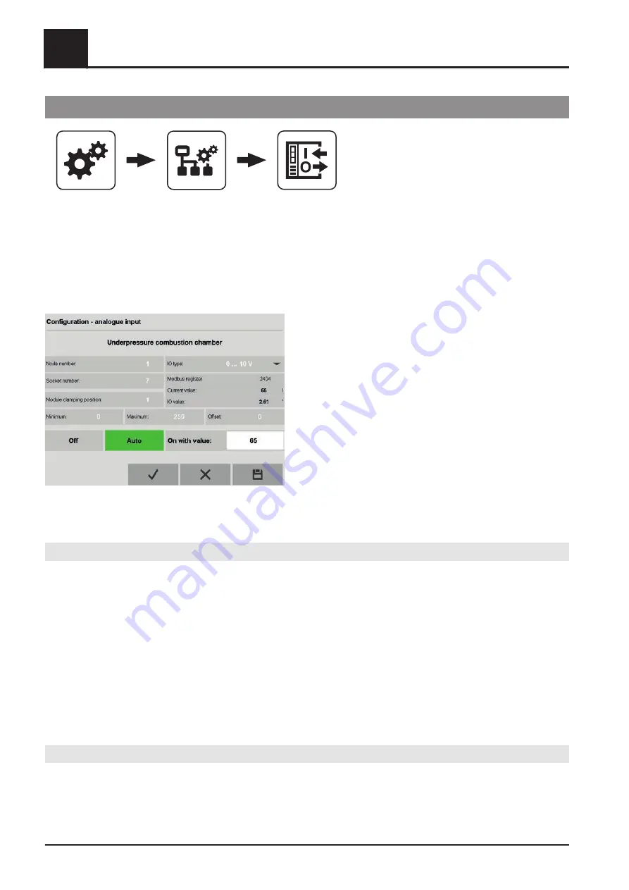
In this menu, inputs and outputs are assigned to the ports of the I/O cards in the SPS rack.
❒ Open the relevant submenu (analogue, digital, etc.)
❒ Tap the desired input/output to change it
➥ The configuration window will open
The following settings are available:
Node number
Setting range: 0-255 (“0” and “255” = not configured)
The node number defines the socket and terminal of the same card type. The cards do not have to be placed
side by side in the rack, but can be separated by any number of other card types.
Example 1: 3x DI cards in sockets 3, 7 and 9
The first DI card (DI9371, 12 channels) has node numbers 1-12, the second 13-24 and the third 25-36. The
highest node number of the same card type is therefore:
Number of modules x channel number
Example 2: Node number 11 at PT100 temperature inputs
PT100 temperature input card (AT4222, 4 channels). Node number 11 therefore refers to terminal 3 of the third
AT4222 card (4+4+3 = 11).
Socket number
Card socket in the rack from left to right, starting with a BR9300 module at socket number 1.
5
Menus and parameters
System configuration
86
Fröling GesmbH | A-4710 Grieskirchen, Industriestraße 12 | www.froeling.com


