

3
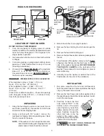
LID OPEN 90°
FRONT VIEW
SIDE VIEW
DRAIN
OUTLET
DRAIN
OUTLET
(REAR)
WATER
INLETS
(REAR)
LOCATION OF YOUR WASHER
DO NOT INSTALL YOUR WASHER:
1.
In an area exposed to dripping water or outside
weather conditions. The ambient temperature should
never be below 60 degrees F (15.6 degrees C) for
proper washer operation.
2.
In an area where it will come in contact with curtains
or drapes.
3.
In an area (garage or garage-type building) where
gasoline of other flammables are kept or stored
(including automobiles).
4.
On carpet. Floor
MUST BE SOLID
with a maximum
slope of 1 in. (2.54 cm). To ensure vibration or
movement does not occur,
REINFORCEMENT
of
the floor may be necessary.
IMPORTANT
MINIMUM INSTALLATION CLEARANCES
When installed in alcove: Sides = 0" (0 cm),
Rear = 0" (0 cm), Top = 20" (50.8 cm).
When installed in closet:
Sides = 0" (0 cm),
Rear = 0" (0 cm), Top = 20" (50.8 cm), Front = 1"
(2.54 cm).
Closet door ventilation required: 2 louvered openings
each 60 square inches (387 cm
2
) — 3 inches (7.6 cm)
from bottom and top of door.
UNPACKING
1.
Using the four shipping carton corner posts (two on
each side), carefully lay the washer on its left side
and remove foam shipping base.
2.
Using a ratchet with 3/8" socket, remove the
mechanism shipping bolt and plastic spacer block
from the center of the base.
NOTE:
If the washer is to be transported at a later
date, the tub blocking pad, shipping bolt, and
plastic spacer block should be retained.
MECHANISM
SHIPPING
BOLT
PLASTIC
SPACER
BLOCK
SHIPPING BLOCKS
DRAIN HOSE
POWER
CORD
FOAM
SHIPPING
PAD
SHIPPING CARTON
CORNER POSTS
3.
Return the washer to an upright position.
4.
Remove the tape holding the lid shut and open the
lid.
5.
Remove the foam tub blocking pad.
6.
Remove the inlet hoses and enclosure package from
the tub.
7.
From the back of the washer, remove only the WIRE
shipping clips that secure the drain hose to the left
side of the washer backsheet.
DO NOT REMOVE
THE PLASTIC CLAMPS
on the right side of the
washer. These clamps form a standpipe to prevent
water siphoning.
8.
Carefully move the washer to within 4 feet of the
final location for the start of the installation.
INSTALLATION
1.
Run some water from the hot and cold faucets to
flush the water lines and remove particles that might
clog up the water valve screens.
2.
Remove the inlet hoses and rubber washers from
the plastic bag and install the rubber washers in each
end of the inlet hoses.
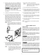
3.
Carefully connect the inlet
hose marked "HOT" to the
bottom outlet of the water
valve. Tighten by hand, then
tighten another 2/3 turn with
pliers. Carefully connect the
other inlet hose to the top
outlet of the water valve.
Tighten by hand, then tighten
another 2/3 turn with pliers.
DO NOT CROSS THREAD OR
OVERTIGHTEN THESE CONNECTIONS.
ROUGH-IN DIMENSIONS
27"
27"
3-3/4"
(129.54
cm)
(9.53 cm)
(68.58 cm)
(68.58 cm)
(74.77 cm)
29-7/16" (111.76
cm)
44"
51"
(29.05 cm)
←
11-7/16"