28
PB
OPERATION
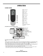
Figure 301
Remote Control Button Identification
69700657 / 69700623
Introduction for icons on display screen
5
3
6
8
10
12
11
9
7
4
2
1
1
2
3
4
5
6
7
8
9
10
11
12
ON/OFF button
MODE button
FAN button
SWING button
TURBO button
TEMP button
WiFi button
LIGHT button
CLOCK button
TIMER ON / TIMER OFF
button
SLEEP button
▲
▲
/ button
Set time
TIMER OFF
TIMER ON /
Child lock
Send signal
Turbo mode
8 heating function
Set temperature
Up & down swing
Set fan speed
Light
Temp. display type
:Set temp.
:Outdoor ambient temp.
bient temp.
Sleep mode
Clock
Temp. display type
:Indoor am
Heat mode
Fan mode
Dry mode
Cool mode
Auto mode
I feel
Operation mode
WiFi
This is a general remote controller.Some
models have this function while some
do not. Please refer to the actual models.
{
Introduction for buttons on remote controller
Note:
●
This is a general use remote controller, it could be used for the air conditioners with multifunction; For some function, which the
model doesn't have, if press the corresponding button on the remote controller that the unit will keep the original running status.
●
After putting through the power, the air conditioner will give out a sound. Operation indicator "
" is ON (red indicator, the colour is
different for different models). After that, you can operate the air conditioner by using remote controller.
●
Under on status, pressing the button on the remote controller, the signal icon " "on the display of remote controller will blink once
and the air conditioner will give out a “de” sound, which means the signal has been sent to the air conditioner.
●
Under off status, set temperature and clock icon will be displayed on the display
of remote controller (If timer on, timer off and light functions are set, the corre- sponding icons will be displayed on the display of
remote controller at the same time); Under on status, the display will show the corresponding set function icons.
Summary of Contents for FSHW091
Page 8: ...8 INTRODUCTION FSHSW09A1A FSHSW12A1A Figure 102 Indoor Units FSHSW18A3A FSHSW24A3A FSHSW36A3A ...
Page 47: ...47 INSTALLATION ...
Page 48: ...48 INSTALLATION Installation Tools ...
Page 72: ...72 WIRED CONTROLLER Display ...
Page 122: ...122 TROUBLESHOOTING Malfunction of IDUFanMotorU8 Service Manual No Start End ...
Page 146: ...146 WIRING DIAGRAMS Figure 8054 9 12KOutdoorUnitWiringDiagrams 60000706067401 3 2 N 1 C3 C4 ...
Page 158: ...158 FIgure 906 PARTS CATALOG 9KOutdoorUnit 28 27 29 31 30 32 ...
Page 160: ...160 PARTS CATALOG 12k OutdoorUnit 28 27 29 31 30 32 FIgure 907 ...

