


VYPER
™
VARIABLE SPEED DRIVE
MAINTENANCE
100-200 IOM (FEB 09)
Page 58
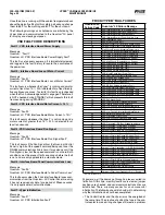
Fault 50: Harmonic Filter High DC Bus Voltage
Message
Quantum: “Fault 50”
Quantum LX: “Harmonic Filter High DC Bus Voltage Fault”
The harmonic filter’s DC link voltage is continuously moni-
tored and if the level exceeds a range of 822 to 900 VDC, a
Filter Bus Over-Voltage shutdown is initiated. Keep in mind
that the harmonic filter has its own DC bus as part of the
filter power unit, and this DC Link is not connected in any
way with the drive’s DC Link. If this shutdown occurs, it will
be necessary to look at the level of the 460 VAC applied to
the drive. The specified voltage range is 414 to 508. If the
incoming voltage is in excess of 508, steps should be taken
to reduce the voltage to within the specified limits. The cause
of this message will typically be high line voltage, or a surge
on the utility supply.
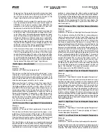
Fault 51: Harmonic Filter High Phase C Current
Message
Quantum: “Fault 51”
Quantum LX: “Harmonic Filter High Phase C Current Fault”
The three output lines from the 519 filter to the three phase
output inductor are monitored via two Hall effect DC current
transformers (DCCT1 and DCCT2) within the drive. The third
phase is derived using the equation I
f2
= -I
f1
+I
f3
. The unit’s
three phases of instantaneous output current are compared
to a prescribed limit, which is contained in hardware. If any
one of these three signals exceeds the prescribed limit,
the filter will be inhibited from operating by inhibiting the
Current Regulator Run signal for five to six input line volt-
age. If any one of the three signals exceeds the prescribed
threshold three times in 60 line cycles, the unit will trip and
the Quantum
™
LX panel will display the message Fault 51.
The peak current levels seen by the IGBT’s under an over-
current trip condition are as follows: 305 Hp (60 Hz) / 254
Hp (50 Hz) = 378 + 59 Amps.
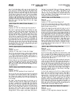
If you experience this shutdown and the Vyper
™
auto-restarts
and continues to run properly with the filter operating, it is
likely the filter tripped on over-current due to a sag or surge
in the voltage feeding the chiller. If this message reoccurs,
preventing the unit from restarting, you will need to check
the filter power unit for shorted transistors. This is done by
measuring resistance from wires 519, 518, and 517 to the
filter’s positive bus, checking in both polarities - and from 519,
518, and 517 to the filter’s negative bus in both polarities.
None of the readings should be less than 5 ohms.
Fault 52: Harmonic Filter High Phase B Current
Message
Quantum: “Fault 52”
Quantum LX: “Harmonic Filter High Phase B Current Fault”
Same as Fault 51 except for applying to Phase B.
Fault 53: Harmonic Filter High Phase A Current
Message
Quantum: “Fault 53”
Quantum LX: “Harmonic Filter High Phase A Current Fault”
Same as Fault 51 except for applying to Phase B.
Fault 54: Harmonic Filter Phase locked loop
Message
Quantum: “Fault 54”
Quantum LX: “Harmonic Filter Phase Locked Loop Fault”
This shutdown indicates that a circuit called a “phase locked
loop” on the Filter Logic board has lost synchronization with
the incoming power line for a period of time. This is normally
an indication that one of the Filter’s incoming power fuses is
blown. Check filter power fuses 8FU, 9FU and 10FU if this
shutdown occurs. If the fuses are OK, then check the output of
the line voltage isolation board at connector J5, pins 1, 2, and 3
on the Filter logic board. With 480 VAC present on the input to
the line voltage isolation board, approximately 5.2 VAC should
be present from pins 1 to 2, pins 2 to 3, and pins 3 to 1.
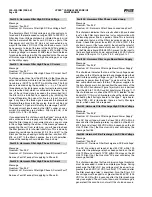
Fault 56: Harmonic Filter logic Board Power Supply
Message
Quantum: “Fault 56”
Quantum LX: “Harmonic Filter Logic Board Power Supply”
This shutdown indicates that one of the low voltage power
supplies on the Filter Logic board have dropped below their
permissible operating voltage range. The filter logic board
receives its power from the Vyper
™
Logic board via the rib-
bon cable which connects the two. The power supplies for
the logic boards are in turn derived from the secondary of the
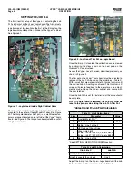
120 to 24 VAC transformer (Figure 7a) which in turn is derived
from the 480 to 120 VAC control transformer (Figure 7). If
this shutdown occurs, check the CR10 LED, labeled “Power
Supply OK”. If this is not illuminated, check the ribbon cable
connecting the filter logic board to the Vyper
™
logic board.
If the CR10 LED is illuminated, there is a faulty filter logic
board, which needs to be replaced.
Fault 65: Harmonic Filter Precharge High DC Bus Voltage
Message
Quantum: “Fault 56”
Quantum LX: “Harmonic Filter Logic Board Power Supply”
The DC link voltage will reach at least 525 VDC within 5
seconds after the precharge relay is pulled in on the 60 Hz
519 filter and at least 425 VDC within 5 seconds on the 50
Hz 519 filter. If not, the Quantum
™
LX panel will display the
message Fault 65.
Fault 66: Harmonic Filter Precharge low DC Bus Voltage
Message
Quantum: “Fault 66”
Quantum LX: “Harmonic Filter Precharge Low DC Bus Voltage”
The DC link voltage will reach at least 50 VDC within 100
msec after the precharge relay has been pulled in on the 60
Hz 519 filter and at least 41 VDC within 100 msec on the 50
Hz 519 filter. If not, the Quantum
™
LX panel will display the
message Fault 66.
This shutdown requires that two minimum voltage thresholds
must be exceeded in order to complete precharge. During
precharge the filter’s DC bus voltage must be equal to or
greater than 50 VDC (41 VDC for 50 HZ) 1/10 second after
the filter precharge relay is energized. Also, the filter’s DC
bus voltage must be equal to or greater than 525 VDC (425
VDC for 50 HZ) within 5 seconds after the filter precharge
relay is energized. The unit is shut down, and this message is
generated if this condition is not met. If this shutdown occurs,