


VYPER
™
VARIABLE SPEED DRIVE
OPERATION
100-200 IOM (FEB 09)
Page 45
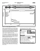
With the actual pressure at 21 psig the proportional com-
ponent would be 20%. The Proportional Component is
calculated as:
[(Actual Value – Setpoint) / PB] x (Maximum output – Mini-
mum Output).
[(21 – 20) / 4] x (100 – 20) = 20%
When this proportional component is added to the mini-
mum outpoint setpoint, the total output is 40% propor-
tionally at an actual value of 21 psig. It is the Integration
Time setpoint which will increase the output over time
without an increase in the actual value.
As long as the actual value (21 psig) does not change, the
Integration Time setpoint, in this case [30 sec], will increase
the output by the proportional component over every 30 sec-
onds to drive the actual value back to the Capacity Control
setpoint. If the actual value remains 21 psig, the Integration
Time Setpoint would increase the drive output to 100% over
1.5 minutes. (See Figure 50).
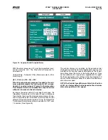
This control strategy is a variation on the generic control
strategy shown previously. Not all applications require or are
suitable for the very low speeds obtainable by the Vyper
™
drive. Many times the motor is the limiting factor as it may
not be suitable for 20% speed but is capable of 50% speed.
For these applications, the settings within the Quantum
™
LX
can assure that the motor never runs slower than the allow-
able minimum speed.
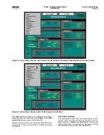
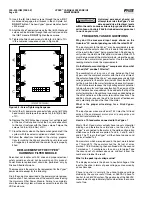
NOTE: The Variable Speed Minimum Slide Valve Position
of 25% is a factory default value based on the minimum
slide valve position at 50% speed.
Figure 50 - Capacity Control Setpoints Screen