


RWB II ROTARY SCREW COMPRESSOR UNITS
INSTALLATION
S70-200 IOM
Page 14
ECONOMIZER LOAD BALANCING
The most energy efficient manner to operate an economizer
system, when using multiple compressors on a common
economizer vessel, is to take as much of the flash gas as
possible to the compressors that are fully loaded. This can
be done in at least two ways.
1. Use the economizer output from the microprocessor to
turn off a solenoid, or to actuate the electric shutoff option on
a back-pressure regulator, based on percent of slide valve
travel. This will direct all the flash vapor to the other loaded
compressors.
2. A dual-setpoint back-pressure regulator valve can be used
in each of the individual economizer vapor lines. When a
compressor is running near full load, the BPR valve will op-
erate on the desired setpoint, or basically wide open, to mini-
mize pressure drop in the line. When one compressor un-
loads below the slide valve position where the economizer
output on the microprocessor turns on, the dual-setpoint fea-
ture of the regulator can be actuated by this output to control
the pressure, on the vessel side of the regulator, to be a few
psi higher. Consequently, the flash gas will be sent to the
loaded compressors first, until they can’t handle all the va-
por and the pressure in the vessel starts to rise. Then, some
of the vapor will go to the unloaded compressor to help main-
tain the vessel at the desired pressure. An example of a back-
pressure regulator with electric shutoff and the dual-setpoint
feature is an R/S A4ADS.
ELECTRICAL
NOTE: Before proceeding with electrical installation, read
the instructions in the section “Proper Installation of Elec-
tronic Equipment in an Industrial Environment”.
RWB II units are supplied with a
QUANTUM control system.
Care must be taken that the controls are not exposed to physi-
cal damage during handling, storage, and installation. The
single-box control door must be kept tightly closed to pre-
vent moisture and foreign matter from entry.
NOTE: All customer connections are made in the single-
box control mounted on the oil separator. This is the
ONLY electrical enclosure and it should be kept tightly
closed whenever work is not being done in it.
MOTOR STARTER PACKAGE
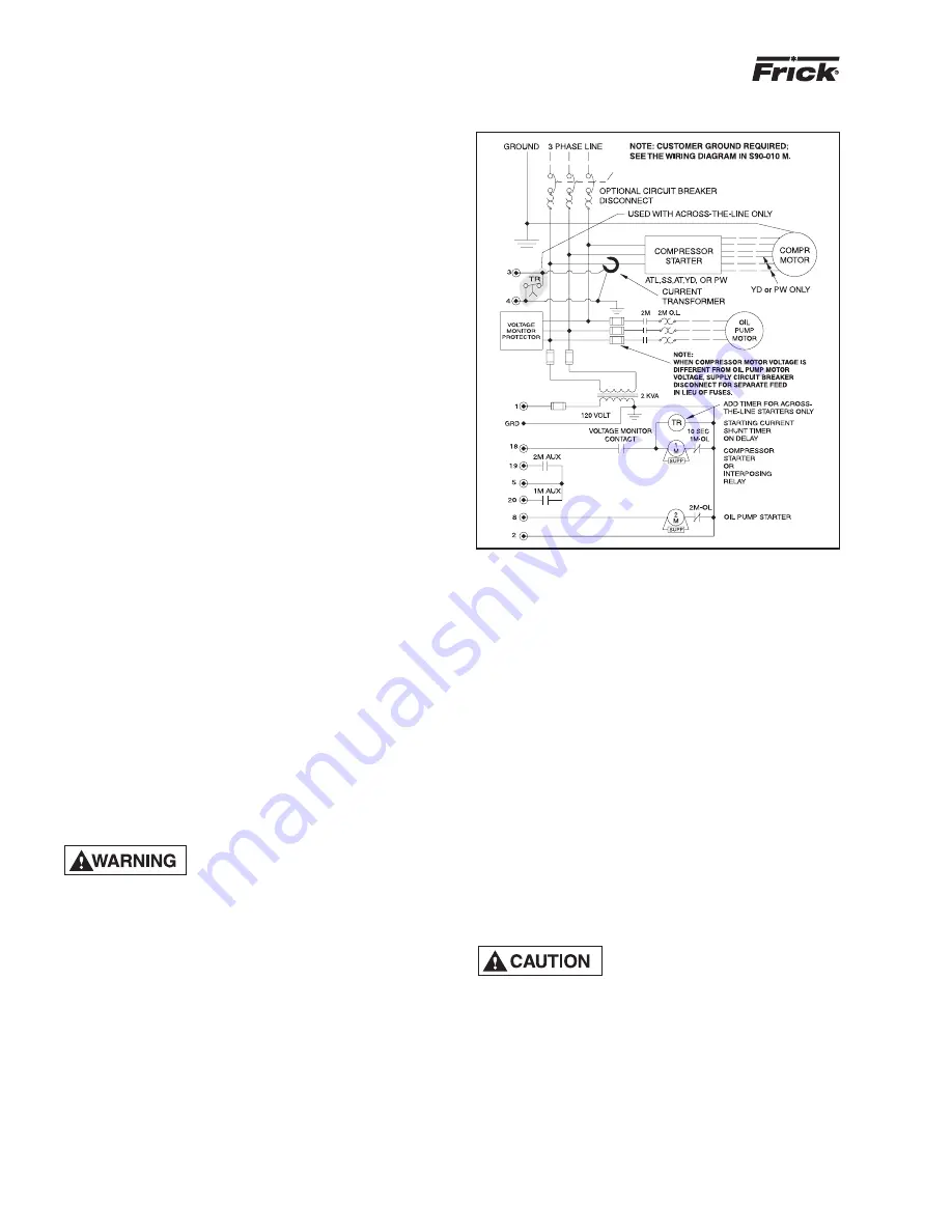
SBC Board damage may occur
without timer relay installed in
control panel as shown in Starter
Wiring Diagram, Figure 15. All Frick motor starter pack-
ages have the timer relay as standard.
Motor starter and interlock wiring requirements are shown in
the Starter Wiring Diagram. All of the equipment shown is
supplied by the installer unless a starter package is pur-
chased separately from Frick . Starter packages should con-
sist of:
1. The compressor motor starter of the specified HP and
voltage for the starting method specified (across-the-line, au-
totransformer, wye-delta, or solid state).
NOTE: If starting methods other than across-the-line are
desired, a motor/compressor torque analysis must be
done to ensure that sufficient starting torque is avail-
able, particularly in booster applications. Contact FRICK
if assistance is required.
2. If specified, the starter package can be supplied as a com-
bination starter with circuit breaker disconnect. However, the
motor overcurrent protection/disconnection device can be ap-
plied by others, usually as a part of an electrical power distri-
bution board.
3. The oil pump starter with fuses, or in the case where the
compressor motor is a different voltage from the oil pump
motor, with a circuit breaker disconnect suitable for separate
power feed.
4. A 2.0 KVA control power transformer (CPT) to supply 120
volt control power to the microprocessor control system and
separator oil heaters is included. If environmental conditions
require more than the usual two 500 watt oil heaters, an ap-
propriately oversized control transformer will be required. If
frequent power fluctuations are anticipated or extremely noisy
power lines are encountered, a regulating control transformer
should be considered. Contact FRICK for assistance.
5. For customer-supplied across-the-line starters, a shunt-
ing device must be installed across the Current Transformer
(terminals 3 & 4).
If the shunting device is not in-
stalled, the Analog I/O board on the
Quantum panel may be severly
damaged at start-up (see Starter Wiring Diagram,
Figure 15).
6. One each normally open compressor motor and oil pump
motor starter auxiliary contact should be supplied. In addi-
tion to the compressor and oil pump motor starter coils, the
CT and CPT secondaries should be wired as shown on the
starter package wiring diagram. The load on the control panel
for the compressor motor starter coil should not exceed a
Nema size 3 starter. For larger starters, an interposing relay
must be used to switch the compressor motor starter coil(s).
NOTE: Do not install a compressor HAND/OFF/AUTO
STARTER WIRING DIAGRAM
Figure 15


