background image

190.210-IOM (SEP 21)

Page 15

LazerWeld II Plate Heat Exchanger

Maintenance

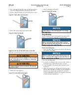
1.  Drain the LZWII.

Figure 26: Drain the LZWII

2.   Brush the threads of the bolts clean, using a steel wire 

brush or the Frick thread cleaner. Lubricate the threads 

with a thin layer of grease, such as Gleitmo 800 Lubri

-

plate or equivalent.

Figure 27: Brush the threads

3.   Inspect the sliding surfaces of the carrying bar and 

clean and grease it.

Figure 28: Inspect the carrying bars 

4.   Mark the cassette assembly on the outside with a 

diagonal line.

Figure 29: Cassette assembly

5.  Measure and note the dimension A.

Figure 30: Dimension A

NOTICE

Brush the threads of the tightening bolts with a steel-
wire brush and then grease before loosening them.

6.   Keep the four bolts in position, according to the follow-

ing figure. Loosen the other bolts and remove them.

Figure 31: Loosen the bolts

Keep the two 
bolts closest 
below the upper 
port holes

Keep the two 
bolts closest 
above the lower 
port holes

Mark

Inspect

Summary of Contents for LaZerWeld II

Page 1: ...al injury or death damage to the unit or incorrect operation LaZerWeld II Plate Heat Exchangers LZWII 2M LZWII 4B LZWII 4E LZWII 6B LZWII 8K LZWII 8B and LZWII 12M Check www FrickCold com for the latest version of this publication Form 190 210 IOM SEP 2021 Installation Operation Maintenance File Service Manual Section 190 Replaces 190 210 IOM FEB 2020 Distribution 3 3a 3b 3c ...

Page 2: ... Nameplate 5 Function 5 Identifying the plate side 6 Installation Before installing 7 Requirements 7 Space 7 Foundation 7 Elbow 7 Shut off valve 7 Connections in the pressure plate 7 Drip tray optional 7 Lifting 7 Raising 8 Connecting to the system 9 Operation Starting the unit 11 Operating the unit 12 Shutting down the unit 12 Maintenance Preventive maintenance guidelines 13 Monitor the status of...

Page 3: ...ick Representative for advice Report the date when the heat exchanger was put into operation to the local Frick Representative Advice Consult your local Frick representative for information on the following New plate pack dimensions if you intend to change the number of cassettes twin plates Selection of gasket material if operating temperatures and pressures are permanently changed or if another ...

Page 4: ...the media to enter into or exit from the heat exchanger Different types of connections can be used to connect the piping system to the apparatus Threaded stud bolts around the port holes secure the connections to the apparatus The port holes may be protected against corrosion by metal linings The LZWII can be equipped with different connection types For details refer to LZWII drawings supplied wit...

Page 5: ...ssembly drawing are to be exceeded consult the supplier Figure 2 Nameplate Material No FRICK Sales Order No Tag No Optional FOR PARTS SERVICE AND AFTER MARKET ASSISTANCE CALL 1 717 762 2121 www frickcold com Function The LZWII consists of a set of corrugated metal plates with port holes for inflow and outflow of two separate fluids The plates are arranged as cassettes twin plates in such a way tha...

Page 6: ... the letter A or the model name in some cases both at the top of the plate See Figure 4 The separate ring gaskets always point to the right when the cassette is oriented as A Figure 4 Plate side identification End cassette II End single plate Channel cassettes End cassette I End single plate Gasketed channel created between two cassettes blue Two plates that form the welded channel inside the cass...

Page 7: ...wing Foundation Install on a flat foundation giving enough support to the frame Elbow To allow easier disconnection of the LZWII connect an el bow to the pressure plate using a flange directed upwards or sideways and with another flange located just outside the contour of the heat exchanger Shut off valve In order to open the LZWII install shut off valves at all connections Connections in the pres...

Page 8: ...ce for LZWII 12M Raising This instruction is valid when raising the LZWII after delivery The strap is approved for the weight of the heat exchanger to be used CAUTION The straps are long enough to rotate the PHE without obstructions Pay particular attention to the space required for the support column 1 Place two timber posts on the floor Figure 11 Timber posts 2 Lift the LZWII off the pallet usin...

Page 9: ...to the system Before connecting any piping complete the following Ensure that no foreign objects have been left in the system that connects to the LZWII Remove the sealing blind covers from the port holes When connecting the piping system complete the follow ing steps 1 Ensure the pipes do not subject the LZWII to stress or strain 2 Install a strainer or filter with 0 5 mm to 1 0 mm mesh size to p...

Page 10: ...190 210 IOM SEP 21 Page 10 LazerWeld II Plate Heat Exchanger Installation This page is intentionally left blank ...

Page 11: ...peratures Such temperature levels might be lower than any elasto meric materials can seal against In applications where the field side is used for a two phase refrigerant for example cascade CO2 NH3 ap plications it is very important to fill the two phase refrigerant in gas phase This to avoid temperature chocks for the gaskets and to avoid temporary leak ages due to the natural fact that the meta...

Page 12: ...ratures and pressures are within the limits stated on the LZWII drawing and identification plate Shutting down the unit If several pumps are included in the system make sure you know which one to stop first 1 Slowly close the valve controlling the flow rate of the pump you are about to stop Figure 22 Close the valve to pump 2 After closing the valve stop the pump 3 Repeat Steps 1 to 2 for the othe...

Page 13: ...ses and the condensation temperature increases from startup condi tions 2 F in higher temperature difference ΔT between evapo ration condensation and coolant increases the required energy input to the compressor by approximately 3 For example by cleaning a fouled SWPHE and reducing the ΔT by 2 F the energy savings come to 45 000 kWh year with a 400 HP motor running 5 000 h year With a cost per kWh...

Page 14: ...uch as safety boots safety gloves and eye protection when using the cleaning agents WARNING Corrosive cleaning liquids can cause serious injuries to skin and eyes See the specifc CIP equipment instructions for cleaning procedures Frick guarantees that plates cassettes gaskets and ad hesive cannot be damaged if the procedures and cleaning agents specified are used If CIP is inappropriate cleaning m...

Page 15: ... bar and clean and grease it Figure 28 Inspect the carrying bars 4 Mark the cassette assembly on the outside with a diagonal line Figure 29 Cassette assembly 5 Measure and note the dimension A Figure 30 Dimension A NOTICE Brush the threads of the tightening bolts with a steel wire brush and then grease before loosening them 6 Keep the four bolts in position according to the follow ing figure Loose...

Page 16: ...otective sheets NOTICE Number the cassettes before removing them Cassettes do not need to be removed if cleaning is done using only water or without cleaning agent Figure 34 Remove the cassettes WARNING The plate pack may still contain a small residual amount of liquid after draining Depending on the type of product and type of installation special ar rangements such as drainage box may be necessa...

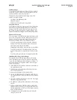
Page 17: ... to the cleaning agents can damage the gasket glue Regasketing These procedures apply to field gaskets and ring gaskets affixed to the cassettes using glue free clip on tabs NOTICE Before removing the old gaskets check how they are placed and attached Especially the end cassette gasket configuration needs attention Clip on and clip grip 1 Open the LZWII see Opening and remove the cassette that nee...

Page 18: ...You do not need to remove any old tape because the film is very thin Ensure that the gasket groove is clean and dry however 4 Apply tape using the tape gun Figure 40 Regasketing the cassette 5 Attach the gasket to the cassette The gasket place ment of the respective cassette type can be advised by your Frick representative 6 Close the heat exchanger see Closing Glued gaskets Use glue suggested by ...

Page 19: ...led the edges form a honeycomb pattern See the following figure Figure 43 Honeycomb pattern 6 Press the plate assembly together Tightening is done in two steps See the following substeps Be careful to ensure that the frame plate and the pressure plate are always in parallel a Tighten the two diagonal pairs of bolts alternately until the plate package measures 1 10A Ensure that the frame plate and ...

Page 20: ...for refrigeration applications and units with me dia not mixable with water must be dried after hydrostatic pressure testing If refrigerants are in the welded channels they must be tested with inert gas such as N2 Consult the local office representative of the supplier for advice on the pressure testing procedure Storing the LZWII Frick delivers the LZWII ready to be put into service upon arrival ...

Page 21: ...th media sides of the LZWII Depending on the media rinse and then dry the LZWII Cover the connection if the piping system is not con nected Use a plastic or plywood cover for the connec tion Cover the plate pack with non transparent plastic film Installing after long term storage In cases when the LZWII has been taken out of service for an extended period of time for example longer than 1 year the...

Page 22: ...e 14 Added Backflushing and Reconditioning at an authorized center Page 20 Updated Table 2 Johnson Controls 100 Cumberland Valley Avenue Waynesboro PA 17268 1206 USA Phone 717 762 2121 FAX 717 762 8624 www johnsoncontrols com Frick Form 190 210 IOM 2021 09 Supersedes 190 210 IOM 2020 02 Subject to change without notice Published in USA 09 21 PDF 2021 Johnson Controls All Rights Reserved ...

Reviews: