


HPS Rotary Screw Compressor Units
070.700-IOM (MAR 21)
Page 21
Operation
Operation
Operation and Start-Up instructions
The HPS rotary screw compressor unit is an integrated
system consisting of seven major subsystems:
• Quantum
™
HD control panel
(See publications
090.040-O, -M, and -CS
)
• Compressor
• Compressor lubrication system
• Compressor oil separation system
• Compressor hydraulic system
•
Compressor oil cooling system
• Compressor easy-start system
The information in this section provides logical
step-by-step instructions to correctly start up and operate
the HPS rotary screw compressor unit.
Notice
The following subsections must be read and under-
stood before attempting to start or operate the unit.
HPS compressor
The Frick HPS rotary screw compressor uses mating
asymmetrical profile helical rotors to provide a continuous
flow of vapor and is designed for primarily high-pressure
applications. The compressor incorporates the following
features:
•
Designed for
variable speed drive from 600 rpm to
6,000 rpm.
• No slide valve for
capacity regulation - just a simple
robust capacity control plug valve to reduce starting
torque requirement and provide overload protection.
Plug valve is operated with a 4-way solenoid valve.
•
Fixed volume Vi ratio: 1.4, 1.7, 2.2, 2.9 and 4.0 are avail
-
able as standard. There is no moveable slide stop or
slide valve.
•
High capacity roller bearings to carry radial loads at
both the inlet and outlet ends of the compressor.
•
Heavy-duty, four-point contact ball, or angular-contact
bearings are mounted at the discharge end of the com
-
pressor to carry axial loads.
• Balance piston located in the inlet end of the male rotor
reduces axial loads on the male axial bearings.
•
Housings are designed for 970 psig maximum working
pressure.
• Economizer port at 1.05 Vi, primarily intended for CO
2
applications.
• Liquid injection port at 1.30 Vi.
• Two main oil injection ports at 1.05 and 1.30 to meet
application requirements.
•
All bearing and control oil vented to lower pressure
locations inside compressor allowing operation without
an oil pump for most applications.
•
Shaft seal housing designed to maintain operating
pressure on seal well below
discharge pressure for
increased seal life.
•
Oil injected into the rotors to maintain good volumetric
and adiabatic efficiency.
•
Shaft rotation clockwise facing compressor drive end,
suitable for all types of drives.
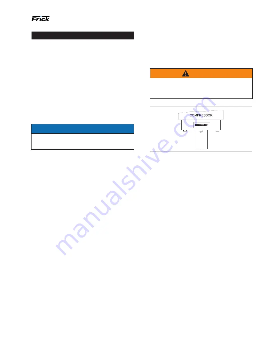
Warning
Compressor rotation is clockwise when facing the
compressor drive shaft (see the following figure).
Never operate the compressor in reverse rotation
because this may result in bearing damage.
Figure 25: Shaft rotation direction
•
Suction flange is ANSI B16.1 Class 400. Discharge flange
is ANSI B16.1 Class 600.
•
Integral
suction strainer.
Compressor lubrication system
The lubrication system on a HPS screw compressor unit
performs several functions:
•
Provides lubrication to bearings and seal.
• Provides a cushion between the rotors to minimize
noise and vibrations.
• Helps keep the compressor cool and prevent overheat-
ing.
• Provides oil supply to hydraulically operate the
plug
valve on and off.
• Provides oil pressure to the balance piston to help
increase bearing life.
• Provides an oil seal between the rotors to prevent rotor
contact or
gas bypass.
No pump oil system
The HPS screw compressor unit is designed to be
self-
lubricating. Oil being supplied to the compres sor from
the oil separator is at system head pressure. Within the
compressor, oil porting to all parts of the compressor
vents back to a point in the compres sor’s body that is at a
pressure lower than compressor
discharge pressure. The
compressor’s normal operation makes the compressor unit
operate essentially as its own
oil pump. All oil entering the
compressor is moved by the compressor rotors out the
compressor outlet and back to the oil separator.
For most applications, an oil pump is not required.