Frick HPS 36 Installation Manual Download Page 19

HPS Rotary Screw Compressor Units

070.700-IOM (MAR 21)

Page 19

Installation

If the electronic control panel has a starter built into 

the same panel, be sure to run the higher voltage wires 
where indicated by the manufacturer.

 EMI from the 

wires can interfere with the electronics if run too close to 
the circuitry.

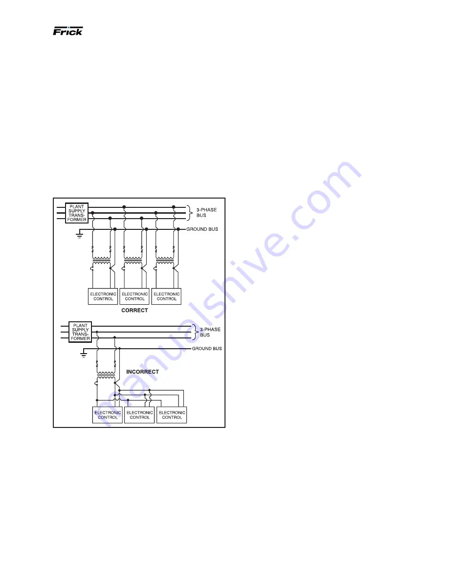
Never daisy-chain or parallel-connect power or ground 
wires to electronic control panels.

 Each electronic 

control panel must have its own control power supply and 

ground wires back to the power source (Plant Transform

-

er). Multiple electronic control panels on the same power 

wires create current surges in the supply wires, which 
may cause controller malfunctions. Daisy-chaining ground 
wires, taking them to ground at each device, allows 
ground loop currents to flow between electronic control 
panels which also causes malfunctions. See the following 
figure.

Figure 24: Daisy-chain wiring example

Communications

The use of communications such as serial and ethernet 
in industrial environments are commonplace. The cor-
rect installation of these networks is as important to the 

operation of the communications as all of the preceding 

practices are to the equipment. 

Serial communications cable needs to be the appropri-

ate gauge based on the total cable distance of the run. 
Daisy-chaining is the only acceptable style of running the 

communications cable. While Star Networks may use less 
cable, they more often than not cause problems and inter-

ruptions in communications, due to varying impedances 

over the varying lengths of cable. Ground or drain wires of 
the communications cable are to be tied together at each 
daisy-chain connection and only taken to ground in the 

central control system panel.

It is important to carefully consider the type of cable to be 
used. Just because a cable has the correct number of con-
ductors and is shielded does not mean it is an acceptable 

cable. Johnson Controls-Frick suggests the use of Belden 

#9829 for RS-422 communications and Belden # 9841 for 

RS-485 up to 2000 ft (609.6 m) total cable length. Refer to 
Frick drawing 

649D4743

 for more detail.

Comm Port Protection:


Surge suppression for the comm 

ports may not be the best method, because suppression 

is required to divert excess voltage/current to ground. The 
success of these devices is dependent on a good ground 
(covered earlier in this section). This excess energy can be 
quite high and without a suitable ground, can access and 
damage the port.

Isolation or Optical Isolation is the preferred comm port 
protection method. With optical isolation, there is no con-
tinuity between the communications cable and the comm 

port. There is no dependence on the quality of the ground. 

Be sure to know what the 

voltage isolation value of the 

optical isolator is before selecting it. These may range 

from 500 V to 4000 V. 

Frick Optical Isolation Kits are available, part number 
639C0133G01. One kit is required for each comm port.

UPS power and Quantum

™ 

HD 

panels

Johnson Controls, Inc. does not advise nor support the 
use of uninterrupted power supply systems for use with 
the Quantum

 HD panel. With a 

UPS system providing 

shutdown protection for a Frick Quantum panel, the panel 

may not see the loss of the 3-phase voltage on the motor 

because the UPS may prevent the motor starter contac-

tor from dropping out. With the starter contactor still 
energized, the compressor auxiliary continues to feed an 
“okay” signal to the 

Quantum

 HD panel. This may allow 

the motor to be subjected to the fault condition on the 
3-phase bus.

A couple of fault scenarios are: 1. The 3-phase bus has 

power “on” and “off” in a continuous cycle manner which 
may cause the motor to overheat due to repeated exces-

sive in-rush current experiences. 2. The motor cycling may 
damage the coupling or cause other mechanical damage 
due to the repeated high torque from rapid sequential 
motor “bumps.” 3. Prolonged low voltage may cause the 

motor to stall and possibly overheat before the motor 
contactor is manually turned off.

Under normal conditions, the loss of 3-phase power shuts 
down the Quantum

™ 

HD panel, restarting upon power 

return. 

•   

Auto

 – The 

compressor motor starts running as pro

-

grammed.

• 

 Remote

 – The external controller would reinitialize the 

panel and proceed to run as required.

Summary of Contents for HPS 36

Page 1: ...tions may result in personal injury or death damage to the unit or improper operation Rotary Screw Compressor Units All Refrigerants Models 36 42 and 60 HPS Form 070 700 IOM MAR 2021 Installation Oper...

Page 2: ...tems 23 Single port liquid injection 23 Suction check valve bypass 23 Low ambient operation 24 Initial start up 24 Initial start up procedure 24 Quantum HD EZ COOL liquid injection adjustment procedur...

Page 3: ...e to superheat the entering vapor tem perature to the compressor to 10 F or 5 6 C above the refriger ant saturation temperature This ensures that all refrigerant at the compressor suction is in the va...

Page 4: ...ERENCE SHEET 2 AND GENERATED BY SAP ASSEMBLY P 534C2933H01 USA US2430129999900010 10241A89999999R 100 CUMBERLAND VALLEY AVENUE WAYNESBORO PA 17268 ROTARY SCREW COMPRESSOR MODEL NO MAX DRIVER SPEED MAX...

Page 5: ...package vibration from be ing transferred to the building structure It may be neces sary to use rubber or spring isolators or a combination of both to prevent the transmission of compressor vibration...

Page 6: ...24 22 30 5 16 18 720C0313H03 58 79 1 2 20 23 31 5 16 24 41 56 3 8 24 22 30 5 16 18 720C0313H04 58 79 1 2 20 23 31 5 16 24 41 56 3 8 24 22 30 5 16 18 720C0313H05 58 79 1 2 20 23 31 5 16 24 41 56 3 8 2...

Page 7: ...ay set screws are tightened before the shaft clamping bolts are tightened then the hubs can be cocked on the shaft Notice Do not use any lubricant on these bolts Holding charge and storage Each HPS co...

Page 8: ...n Controls Frick The heaters are energized only when the unit is not in operation Warning Do not energize the heaters when there is no oil in the unit because the heat ers burn out The oil heat ers ar...

Page 9: ...using refrigerant isolation valves for the oil cooler Notice The component and piping arrangement shown in the following figure is intended only to illustrate the operating principles of thermosyphon...

Page 10: ...the heat exchanger A chemical cleaning process extends the life of the plate and shell heat exchanger It is important to establish regular cleaning schedules Cleaning A 3 solution of phosphoric or oxa...

Page 11: ...compressors run at partial load In the case of a flash vessel there is no need for the redundancy of a back pressure regulating valve on the vessel and each of the multiple compressors Omit the back p...

Page 12: ...ing a smaller check valve is increased pressure drop during full load conditions If ex tended periods of low compressor loading are anticipated use an automated non modulating full port ball valve in...

Page 13: ...Figure 18 Point to point wiring diagram Current transformer CT ratios See the following table for the CT ratio for various motor sizes with a 5 amp second ary Table 6 CT ratios HP Voltage 200 230 380...

Page 14: ...Table 7 Minimum CT burden ratings Burden rating Maximum distance from Frick panel ANSI VA Using 14 Awg Using 12 Awg Using 10 Awg B 0 1 2 5 15 ft 25 ft 40 ft B 0 2 5 35 ft 55 ft 88 ft B 0 5 12 5 93 ft...

Page 15: ...f the three phase wire sizing use Frick drawing 649D4743 as a reference for correctly sizing con trol wires and other wiring specifications Throughout this document the term Electronic Control Panel i...

Page 16: ...le ground potentials and is also a relatively poor con ductor As a result this is not an acceptable method for correct operation of electronic equipment There must be a ground for the three phase powe...

Page 17: ...quirements For variable frequency drives VFD of any type thread ed metallic or threaded PVC coated metallic is required for both the power feed line side from the source and between the VFD output and...

Page 18: ...ectronics and create a short circuit when powered is applied If you must drill the panel take the following precautions First call the panel manufacturer before drilling into the panel to be sure you...

Page 19: ...ft 609 6 m total cable length Refer to Frick drawing 649D4743 for more detail Comm Port Protection Surge suppression for the comm ports may not be the best method because suppression is required to di...

Page 20: ...ng VA rating based on the requirement of the job If a phase loss oc curs a high motor amp shutdown can occur If the prob lem continues an analysis of the facility s power supply quality may be necessa...

Page 21: ...quid injection port at 1 30 Vi Two main oil injection ports at 1 05 and 1 30 to meet application requirements All bearing and control oil vented to lower pressure locations inside compressor allowing...

Page 22: ...rator to develop oil pressure rapidly on initial start in order to lubricate the compressor without requiring an oil pump even in cold ambient temperatures with all pres sures equalized For cascade an...

Page 23: ...oil cooling WCOC or glycol cooled Single port liquid injection The single port liquid injection system is desig ned to per mit liquid refrigerant injection into one port on the com pressor at any giv...

Page 24: ...rge temperature of the compressor After determining this temperature you can adjust the hand expansion valve accordingly The ideal discharge temperature is within 5 F 2 8 C or of the theoreti cal disc...

Page 25: ...arge Temperature is below this setpoint the Liquid Injection solenoid output de energizes until the Discharge Temperature raises above this setpoint EZ Cool status Discharge Temperature The actual Dis...

Page 26: ...ith medium speed according to a digital Input signal High represents that ICAD is operating the ICM valve like an ON OFF solenoid valve with high speed ac cording to a digital input signal See Figure...

Page 27: ...se the VFD speed by 100 rpm increments and physically check the entire package for elevated en ergy at each stage until the minimum speed range is reached 3 As you identify the high energy hot spots c...

Page 28: ...condition at power cut when fail safe is installed 1 Close valve 2 Open valve 3 Maintain valve position 4 Go to OD given by j12 Digital input function j09 1 2 1 Define function when Dl is ON short ci...

Page 29: ...ressor with liquid refrigerant While screw compressors are probably the most tolerant to ingestion of some refrigerant liquid of any compressor type available today they are not liquid pumps Make cert...

Page 30: ...as follows 1 If a single oil filter is installed press the STOP key on the control panel to shut down unit Then open the discon nect switches for the compressor and oil pump motor starters If dual oi...

Page 31: ...tag on the bottom at the 6 o clock position Caution Seat element in center of locating tabs on separator bulkhead 6 Replace the coalescer filter retainer and nut Tighten the nut to 21 ft lb 28 47 N m...

Page 32: ...n As directed by oil analysis Clean oil strainers n n n n n n n n n n n Clean liquid strainers n n n n n n n n n n n Replace coalescers n n n Check and clean suction strainer n n n n n n n n n n n Che...

Page 33: ...leaks abnormal vibration noise and correct operation and maintaining a log Perform the initial oil analysis and vibration analysis at start up and continue as indicated in the Maintenance schedule Vi...

Page 34: ...d by WEG 4 364 L5809 frames Remove and clean bearing caps of excess grease after 8800 hr Procedure Warning With the motor shutdown inject approximately half of the total grease quantity to be used and...

Page 35: ...system may have a tendency to overfeed The high suction superheat condition moreover may only be temporary When system conditions return to normal the unit s liquid injection overfeeds and the oil tem...

Page 36: ...mm the valve can sustain damage In this case it is important to remove only two screws one from each side In the threaded holes from which the two screws have been removed insert studs with nuts and...

Page 37: ...ther The test is complete Replacing pressure transducers 1 Shut off control power 2 Close the applicable transducer isolation valve Notice To change the discharge pressure transducer PE 3 it is necess...

Page 38: ...Shut off control power 2 Remove DIN connector plug from transmitter See Figure 39 3 Unscrew knurled ring and remove transmitter unit 4 Apply thermal compound to new sensor assembly insert into thermal...

Page 39: ...2 Remove the DIN connector plug from the transmitter 3 Loosen the set screws 4 Remove the electronic switch head 5 Install the new electronic switch head 6 Tighten the set screws 7 Apply the DIN conn...

Page 40: ...essor Volumizer ii vi control for further detail Check motor valve operation and calibration Check calibration of analog output Low oil temperature Equalizing pressure too low Raise pressure Suction s...

Page 41: ...O SERIAL NO MAX ALLOWABLE PRESSURE PSIG MAX DRIVER SPEED RPM WAYNESBORO PA 17268 XXX A A SB 3 TRANSDUCER MOUNTING 12 75 502 12 70 500 KEYWAY Discharge Flange 3 Class 600 SD 2 SC 5 SB 2 SD 1 SL 0 BP 1...

Page 42: ...TER ZV POSITION VALVE BP 1 DISCHARGE BYPASS SB 2 INLET BEARING BALANCE PISTON SB 3 DISCHARGE BEARINGS SHAFT SEAL UNLOADER PLUG OIL FEED SC 5 INLET PRESSURE SC 6 DISCHARGE PRESSURE SC 7 SEAL WEEPAGE SC...

Page 43: ...PV 1 HTR 1 HTR 2 4 4 TE TAL C 1 M 1 TE 2 TAH 2 TAHH 2 YY 1 PE 3 PAH 3 CV 1 TE 1 HIGH SIDE COOLING LOAD 4 TALL PAHH 3 NV 1 NV 3 STR 1 2 LG LG 3 1 LSLL 1 LS TI 1 PI 1 HTR 3 SM 1 SC 6 SB 2 SB 3 SC 5 SD 1...

Page 44: ...HPS Rotary Screw Compressor Units 070 700 IOM MAR 21 Page 44 Forms Operating log sheet Cascade Forms...

Page 45: ...compressor motor wiring __ Confirm no high voltage wiring enters the control panel at any point __ Check current transformer for correct sizing and instal lation __ Check all point to point wiring be...

Page 46: ...Serial __________________________ Input Voltage______________ Voltage Range____________ Phase______________ Hz______________ Current_____________ Output Voltage_________ Phase_________ Hz ________ Max...

Page 47: ...When Below _______ Force Unload _____ PSIG _____ PSIG Override Discharge Pressure ________ Warning _____ PSIG _____ PSIG Port Value ________ Warning Delay _____ Sec _____ Sec Pressure Input _________...

Page 48: ...Shutdown_____ gF______ Sec Module B ________ Module C ________ Motor Bearing ______________ Module D ________ Shaft Side Delay Opposite Shaft Side Delay Step Up Dead Band _________PSI High Warning___...

Page 49: ...et______________ Subnet Mask __________ Web Server Port __________ Compressor operating log sheet Starter operating log sheet Date Average current Time Current phase A Hour meter reading Current phase...

Page 50: ...________ Manufacturer and size of coupling _____________________________ Motor manufacturer RAM_____________________________________ Motor serial number _________________________________________ Rpm _...

Page 51: ...3 discharge pressure 21 disconnect switches 29 disc packs 6 disc type check valves 11 drive coupling 23 dry nitrogen 7 29 dual dip tube method 10 dual setpoint 12 DX vessel 11 E economizer back pressu...

Page 52: ...values 36 valve body 36 valve housing 36 stop valve 36 temperature transmitter 37 vibration analysis 33 vibration data sheet 50 vibration readings 33 manual solenoid 31 manway bolts 31 manway cover 3...

Page 53: ...r 23 temperature sensor replacement 39 DIN connector plug 38 thermal well 38 transmitter unit 38 troubleshooting digital board 1 38 thermosyphon 9 thermosyphon oil cooling 9 thermosyphon oil cooling c...

Page 54: ...ue Waynesboro PA 17268 1206 USA Phone 717 762 2121 FAX 717 762 8624 www johnsoncontrols com Frick Form 070 700 IOM 2021 03 Supersedes Nothing Subject to change without notice Published in USA 02 21 PD...

Reviews: