


210.100-IOM (JUL 2018)
Page 46
ACUAIR
®
HYGIENIC AIR UNITS
MAINTENANCE
OPERATING AND MAINTENANCE
INSTRUCTIONS FOR PIEZOMETER
CAUTION
DO NOT PERFORM MAINTENANCE ON THE Piezometer
WHEN FAN IS ROTATING.
Operation of the Piezometer
The Piezometer has no moving parts; it cannot be turned on
or off or adjusted. The ring on the exterior side of the blower
inlet cone as well as the upstream static pressure port are
fitted with a 0.25 union brass tee. The tees are the connection
points for running pneumatic tubing from the Piezometer to
an air pressure gauge.
This Piezometer will automatically produce a pressure
differential signal whenever the fan is moving air. (Figure 54)
Maintenance of the Piezometer
Basic Piezometer maintenance requires keeping the five tiny
pressure pickup holes, in the inlet panel face and the throat of
the inlet cone, free from blockage or debris buildup. Annually
check the tubing and fittings attached outside the Piezometer
for wear or damage.
In addition, it may become necessary to back-flush each line
gently with compressed air. This will help to blowout debris
from inside the line and pressure pickup holes. It is important
and necessary to keep the inside surface of the cone clean;
especially in a one-inch radius immediately around the
pressure pickup holes.
In the unlikely event that the pneumatic tubing on the
Piezometer is damaged, simply remove the damaged section
and replace with a comparable type of tubing.
NOTICE
PRESSURE DIFFERENTIAL ON TUBING IS LESS THAN
1 PSIG.
In the unlikely event that one of the
brass fittings which is
sweated to the Piezometer breaks loose from the Piezometer,
simply remove that fitting and replace it with a straight
coupling fitting of similar construction. Do not attempt to
resolder the fitting to the Piezometer.
There are four pickup holes on the throat of the inlet cone
and one on the upstream face. Elimination of one of the
throat holes will not adversely affect the performance of most
Piezometer. However, obstructing the upstream face hole will
completely nullify its performance.
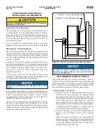
CONNECT TO HIGH PRESSURE SIDE
CONNECT TO LOW PRESSURE SIDE
Figure 54 – Plenum Fan Tap Location And Connection
NOTICE
For help with setup and calibration of Piezometers and
Transducers, contact Johnson Controls-Frick AcuAir
service at 717-762-2121.
RECOMMENDED MONTHLY SERVICE
Along with daily logs and weekly inspections, Johnson
Controls-Frick recommends that the unit undergo a thorough
monthly inspection. The monthly inspection should include
but not limited to the following areas as indicated in the
Recommended Maintenance Interval schedule below:
1. Blowers, Motors, and Drives
a. Shut down the unit , and disconnect all electrical power.
Touch all of the blower bearings. The bearings should
be slightly warmer than the air passing over them, and
they should all be approximately the same temperature.
If any of the bearings are noticeably warmer than the
other bearings, or if any of the bearings are too hot to
touch,
grease should be applied via the grease fitting.
The bearings should be greased in accordance with the
included Blower Bearing Lubrication Guidelines.
b. Verify the tightness of the blower bearing bolts, the
blower, motor, and pulleys, and the motor mounting
bolts.
c. Inspect the blower belt tension. The belts should be
tensioned in accordance with the included Blower Belt
Tension Guidelines. Visually inspect the belts for indica-
tions of wear. Replace the belts if there is evidence of
cracking, fraying, or uneven wear.
Summary of Contents for AcuAir
Page 54: ......