Frick AcuAir Manual Download Page 39

210.100-IOM (JUL 2018)

Page 39

ACUAIR

®

 HYGIENIC AIR UNITS

MAINTENANCE

MAINTENANCE

DAILY OPERATION AND ROUTINE MAINTENANCE

The AcuAir unit should be inspected, cleaned, and lubricated 
on a periodic basis. The required services and recommended 
frequency for the various components are summarized in the 
Operation and Maintenance Schedule in this manual.
A daily AcuAir system operations log is a good method to 
assure that no problems develop that may go unchecked. 
Entries to this log should be made during each shift. Any 
notations should be entered as they occur (or as internal policy 
dictates). It is essential that the maintenance manager examine 
all notations (from the previous 24 hours) on a daily basis.
As weather and safety allow, a visual check of the AcuAir 
unit should be made once each shift (daily at a minimum) to 
examine operating conditions. Unusual leaks, noise, vibration, 
part damage/failures, or vandalism should be logged and 
investigated immediately. Corrective action should be initiated 
immediately.
Components of the AcuAir unit should also be part of the daily 
operational checks conducted of the equipment on site. In 

particular, filtration performance is important for satisfactory 

and problem-free AcuAir hygienic system operation.
The Recommended Maintenance Intervals schedule included in 
the later part of this IOM section should be used to develop the 

site specific hygienic air unit inspection log and maintenance 

schedule.

COIL MAINTENANCE

An AcuAir air unit's operational readiness is dependent on 

the  condition  of  the  fin-coil  heat  exchanger(s).  Coils  that 
are dirty, blocked from airflow, or physically damaged may 

affect overall heat transfer capability of the AcuAir system to 

a significant degree. 

Regular visual inspections should be made of both the inlet and 
leaving sides of the cooling coil(s) as well as the refrigerant 
pipe connections. These inspections should occur at least as 
frequently as indicated in the maintenance schedule in this 
IOM. Remove any airborne debris that may have collected 

on  the  face  of  the  fin  coils.  If  site  conditions  require  coil 

cleaning measures following each of the recommended routine 
inspections it may be necessary to increase the frequency of 
the inspections.  
A typical refrigerated food processing facility has stainless steel 
food contact surfaces and clean work spaces. Evaporators 
trap airborne contaminants and corrosive elements in the 
coils. 

Dirty coils are also unsanitary. They must be cleaned 

regularly with simple, gentle, wash and rinse procedures.

Refrigerant could leak into the process airstream and come 
in contact with food products and personnel. As such, proper 
maintenance of refrigerant coils is essential to prevent 
corrosion and leaks that result in product loss and to ensure 
the safety of plant personnel.
For all coils, chlorine-based cleansing solutions, acidic 
cleansing solutions and highly alkaline cleansing solutions are 
hazardous to the coil's integrity. Use a mildly alkaline cleanser. 
Consult with your chemical supplier and read the Material 
Safety Data Sheet for your cleansing solution.

NOTICE

Air units move air (and airborne contaminants) across 

the coil. Protect the coil from corrosion by washing and 
rinsing frequently.

The water used to wash the coils should be analyzed prior to 
use to determine its suitability. It should not contain dissolved 
chemicals or organisms. Contact a specialist to test the water, 
then follow his recommendations. Establish and follow a 
regular testing and treatment schedule.

Further need for cleaning or repair of an AcuAir

®

 system coil 

should be left to the judgement of a certified or factory-trained 

service person. Contact the local AcuAir

®

 representative if 

a coil or its connections appears to have been significantly 

damaged.

Do not allow ice buildup. If a coil remains partially frosted 
after a defrost, it is unlikely to ever completely remove 
accumulated frost and ice in a subsequent defrost. If a coil 
is allowed to build ice into a solid block, the ice can cause 
stresses to develop which are capable of crushing or rupturing 
coil tubes and piping.


CAUTION

NEVER take shortcuts to clear ice from a coil by applying 
an open flame to melt ice or frost.
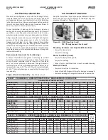
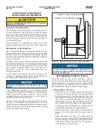
DAMPER MAINTENANCE

1.  General Maintenance 

– Dampers require proper 

maintenance in order to function correctly. Blade shafts, 
linkages, stainless steel side seals (if applicable) and other 
moving parts should be cleaned and lubricated as indicated 
in the Recommended Maintenance Interval schedule in this 
manual. 

A light molybdenum oil in aerosol cans is preferable since the 
jet nozzle permits pinpointing the stream of lubricant where 
required. It usually contains an evaporating solvent and dries 

to a non-oily film, which will not attract dirt. For dampers 
located in difficult or impossible to reach locations, field access 

panels/doors are required as installed by others.

2.  Periodic Inspections

 – All automatic dampers should 

be checked and serviced on a regular schedule. The AcuAir 
recommended interval is monthly and should never exceed 
three months. Malfunctioning dampers can lead to improper 

control  of  space  temperatures,  excessive  infiltration,  and 

increased energy costs.

3. 

Inspection Checklist 

– At a minimum, include the following 

items in scheduled inspections:
•  Observe damper motors and actuators through an operating 

cycle to check for defects and binding. Inspect mounting 
bolts for integrity.

•  Adjust actuator linkages so those dampers open and close 

fully for given stroke.

•  Verify tightness of closed blades – readjust linkage for any 

blades that may not close fully.

•  Replace any damaged blades – clean operating parts.
•  Inspect blade edge and side seal – replace as necessary.
•  Inspect pins, straps, bushings, etc., for wear and replace 

as required.

Summary of Contents for AcuAir

Page 1: ...00 IOM JUL 2017 Dist 3 3a 3b 3c THIS MANUAL CONTAINS RIGGING ASSEMBLY START UP AND MAINTENANCE INSTRUCTIONS READ THOROUGHLY BEFORE BEGINNING INSTALLATION FAILURE TO FOLLOW THESE INSTRUCTIONS COULD RES...

Page 2: ...tended for use by owner authorized operating service personnel It is expected that this indi vidual possesses independent training that will enable them to perform their assigned tasks properly and sa...

Page 3: ...7 WEATHER HOOD CONNECTION DIRECT TO THE ACUAIR FRESH AIR OPENING 28 FILTER INSTALLATION TABLE OF CONTENTS 30 FILTER LATCHES 30 ACUAIR SINGLE FILTER APPLICATION NON HEPA 31 HEPA FILTER APPLICATION 33 N...

Page 4: ...ntrol sequences CAUTION Users and installers of this equipment should be aware of all recommended safety procedures and information such as AMCA publication 410 90 Safety Practices CAUTION Never open...

Page 5: ...ATION MAINTENANCE Figure 1 Access Door Latch 1 25 1 50 LATCH FRONT VIEW LATCH SIDE VIEW DANGER WITH LOCK BOLT OR SCREW PRIOR TO OPERATION SECURE THIS ACCESS OR PROPERTY DAMAGE CAN CAUSE PERSONAL INJUR...

Page 6: ...ied and corrected before testing or placing the system back in operation Wet Surface Precautions Poorly maintained and wetted machinery requires care to avoid electrical shocks from inadequate or loos...

Page 7: ...n pan outlets to a common drain line AcuAir recommends individual p traps The piping design should take into account the pressure inside the specific section and the elevation required to create the n...

Page 8: ...pports at maximum interval of 5 feet 4 Fan wheels should be rotated by hand 90 every month Lightly lubricate bearings every two 2 months 5 A 200 watt light bulb needs to burn continually in each secti...

Page 9: ...ributed causing the section to be unbal anced or top heavy To prepare for safely lifting the air unit estimate the approximate center of gravity Internal placement of components may cause the weight t...

Page 10: ...oads such as water or refrigerant within the cooling and heating coils possible frost on the cooling coils any applicable flooded refrigerant surge vessel and associated piping snow loads that could a...

Page 11: ...IDTH LENGTH AND WEIGHT 2 ALTERNATE METHODS OF SUPPORT TO INCLUDE SUPPORT AT ALL SECTION SPLITS SUPPORT DESIGNED AND SUPPLIED BY OTHERS DRAWING FOR REFERENCE ONLY LEGS TO SUPPORT THE FRAME ABOVE THE FI...

Page 12: ...he local codes Figure 8 Roof Curb Detail SPLIT MIDSPAN GENERAL SPLIT UNIT REASSEMBLY Units which are shipped in sections must be installed on a proper foundation and carefully assembled to provide the...

Page 13: ...ed during transit should realign 7 Once the sections are drawn together and the reconnect flanges are aligned and attached apply two parallel beads of caulk along either side of the reconnect seam on...

Page 14: ...T SEE NOTE 4 RECONNECTION ATTACHMENT AND SEALING PROCEDURE See Figure 11 1 Apply a generous amount of polyurethane caulking to the two faces of the housing and split plate as shown 2 Pull sections tog...

Page 15: ...kit Take special note of the 30 second inactivity limit after which the injection nozzle may become permanently clogged Foam should be injected into the cavity at a rate of 3 4 bd ft per linear foot o...

Page 16: ...hane Caulking Manus bond Gray P N 013 02966 001 Manus bond Champagne P N 013 03317 220 Bostik Gray P N 013 03318 170 Bostik Champagne P N 013 03319 170 Figure 13 Split Reassembly Procedure For AcuAir...

Page 17: ...mperature is between 45 F and 108 F Below 45 F extra steps must be taken to keep the polyurethane caulking Acu Shield and metal reconnect surfaces heated for proper application during installation Con...

Page 18: ...all together and then remove jack from opposite side As the unit settles the out of square racking caused during transit should realign Continue assembly with bolting other side base and roof making u...

Page 19: ...il the split sections are completely reassembled ACUAIR FOOD GRADE OR SANITARY SERIES ROOF RECONNECT FINISH 1 The mechanical joint between the unit sections must be bolted and sealed with polyurethane...

Page 20: ...Split Reassembly Procedure For AcuAir Food Grade and Sanitary Series Units Only 6 Apply Acu Shield Roof Coating with a good quality synthetic bristle paintbrush not provided 7 One quart applied at 45...

Page 21: ...CAULK BASE SKIN BASE CHANNEL INTERNAL WALL FINISH BEAD OF CAULK C L SPLIT SIDE VIEW WHEN INTERNAL WALL IS AT A SPLIT Inject Foam Prior to Installing Cover SPLIT COVER Follow the instructions provided...

Page 22: ...Figure 21 Ensure gun safety is on roller is locked toward end of applicator Pull yellow tab to remove black plastic valve lock Discard Figure 22 Activate valves by pulling black strap up and insert st...

Page 23: ...the plenum into position mount the two brackets using the cap screws provided 5 Prior to placing the hood in the mounting position apply a continuous bead of polyurethane caulking on the face of each...

Page 24: ...esh Air Temperature Sensor Mounting NOTICE Any penetration of cabinet skin will cause water and air leakage Thoroughly seal any screw piping or electrical holes with appropriate sealant Self tapping s...

Page 25: ...er washer Place remaining nuts on studs and tighten to lower nut to lock in place Figure 30 Spring Isolator Setup STUD STUD TUBE TUBE NUTS NUTS SHOULDER WASHER SHOULDER WASHER OPERATING POSITION SIDE...

Page 26: ...of 3 at the drain connection Drain pans and pipe stub outlet connection are constructed of 304 stainless steel unless specified otherwise SLOPE RECESSED HYGIENIC OUTLET SLOPE MPT SLOPE AIRFLOW ACUAIR...

Page 27: ...us tomer s contractor s responsibility to provide adequate evacuation of the evaporator coil and ensure that the coil is dry and water free before start up of the system 5 Water or Brine Coils It is e...

Page 28: ...water and air leakage Thoroughly seal any screw piping or electrical holes with appropriate sealant Self tapping screws are not weather tight Figure 35 Connection of Weather Hood s to Unit Figure 36 W...

Page 29: ...nnections 9 All modified panels must provide integrity equal to original equipment specifications 10 Reconnect any components bulkheads or other fixtures that were disconnected from panel in step 1 11...

Page 30: ...er installed in a standard type 8 filter frame Use with a 4 pleated panel pre filter in a smooth notch free style filter rack NOTICE Typically when filters are supplied by others so are the filter cli...

Page 31: ...s 2 SS Knock on Clip 122 705 002 CA 02s KOCH 122 705 002 4 SS knock on Clip 122 705 004 CA 04s KOCH 122 705 004 12 SS knock on Clip 122 708 012 CF83Fs KOCH 122 708 012 Type 8 Filter Frames Notchless s...

Page 32: ...4 X 12 X 12 DH Same as above Same as above 24 X 24 X 12 DH 110 720 001 Multi Cell SMB 95 KOCH 110 720 001 MERV 16 4V Extended Surface MiniPleat Filter 12 X 24 X 12 DH 111 691 103DH DuraMAX 4V MERV 16...

Page 33: ...11 375 X 11 5 H79A2X1 BioMAX HC KOCH H79A 2X1 11 375 X 23 375 X 11 5 H60A2X1 BioMAX HC KOCH H60A 2X1 99 99 BioMAX HC HEPA MERV 18 Galvanized NOTE H x W x D 23 375 X 23 375 X 11 5 H64A4X1 BioMAX HC KOC...

Page 34: ...of the frame The latch fits into the set of knockouts which consists of two 2 rows of three 3 knockouts The row of knockouts closest to the gasketing should be used for nominal 1 filters or filters w...

Page 35: ...ed like that shown in Figure 42 Figure 42 Frame with 4 latches installed NOTICE The frame contains 2 latches per side none on the top or bottom 5 Insert the rigid DH filter into the frame While holdin...

Page 36: ...may directly compromise the filtration media General concentrated pressure may compromise the media by forcing it against the internal aluminum pleat separators If unprotected HEPA filters are placed...

Page 37: ...c Verify tightness of blower motor and sheave d Verify tightness of all motor mounting bolts 2 Belt Tension a Adjust belt tension if slipping is evident b Verify belt tension after 50 hours of operat...

Page 38: ...ectrical power supply to the furnace 3 Set the burner controls to the OFF position 4 Close the manual gas shutoff valve external to the furnace Figure 46 AcuAir Gas Burner Wrapper 24 Hour Run In After...

Page 39: ...he safety of plant personnel For all coils chlorine based cleansing solutions acidic cleansing solutions and highly alkaline cleansing solutions are hazardous to the coil s integrity Use a mildly alka...

Page 40: ...her of two methods through unsealed conduit ends and flexible conduit pigtails prior to the AcuAir unit factory wiring being reconnected on site or by moisture migrating into unsealed conduits that ar...

Page 41: ...posure to CO2 the passive carbonate layer is not formed If the Zinc hydroxide to carbonate reaction does not take place excessive zinc hydroxide accumulates as a layer of soft white fluffy product of...

Page 42: ...fe Generally lubricate bearings every 1 000 hours of operation or more frequently when exposed to wet location wide temperature variety or severe atmospheric conditions Add grease with manual grease g...

Page 43: ...ER SEVERITY OF SERVICE MULTIPLIER STANDARD 1 0 SEVERE 0 5 EXTREME 0 1 LOW TEMPERATURE 1 0 Lubrication Motor Bearing Lubricant Bearing grease will lose its lubricating ability over time The lubricating...

Page 44: ...s all the load on one side of the belt stretching or breaking the cords on that side After the proper operating tension has been applied to the belts verify the following Parallel position of the shea...

Page 45: ...ensioning shortens belt and bearing life 6 Keep belts free from foreign material which may cause slip 7 Make V drive inspection on a periodic basis Tension belt when slipping is observed Never apply b...

Page 46: ...t fitting and replace it with a straight coupling fitting of similar construction Do not attempt to resolder the fitting to the Piezometer There are four pickup holes on the throat of the inlet cone a...

Page 47: ...ERVALS SPARE PARTS RECOMMENDATIONS Johnson Controls Frick recommends that customers maintain an inventory of spare parts for the AcuAir air unit By maintaining this inventory of spare parts change out...

Page 48: ...steam valve Direct fired burner doesn t light Check setpoint for heat Check OA lockout setpoint lockout should be above OA Temp Check MOA module to see if in AUTO green light if on red light if fuse i...

Page 49: ...y representative will work with you to determine the best available date that a factory technician can be at the job site Factory Start up Assistance will include Testing and calibration of all AcuAir...

Page 50: ...r unit mounted within roof slope limitations where applicable Air hoods installed properly Package Installed According to 090 400 SB Proper Installation of Electronic Equipment Terminal screws and wir...

Page 51: ...al Maintenance 39 grease 42 43 46 grease fittings 43 Grease Relief Plug 43 guards 6 H heater 38 HEPA 8 HEPA FILTERS 30 36 hood 28 hoods 23 HVACR contractors 6 I Inspection 37 Inspection Checklist 39 i...

Page 52: ...span callout to Figure 8 p 16 Updated polyurethane caulking options p 20 Updated polyurethane caulking options p 26 Revised Hat Channel terminology p 29 Removed Tube Steam Heat Coil section p 30 Updat...

Page 53: ...based upon the unit being stored indoors in a vibration free non corrosive environment Special provisions may be necessary for environmental conditions outside these parameters Please contact Johnson...

Page 54: ......

Page 55: ...s may be done by telephone or in person but should be confirmed in writing If assistance is needed with the claim process contact your JCI Sales person 3 Touch up any paint that has worn or chipped of...

Page 56: ...conduit openings through the panel enclosure are completely sealed Install desiccant packet sized for panel Install C I 9 AcuAir Quantum or A B Control panel Assure all conduit openings through the p...

Page 57: ...ccant to absorb moisture 1 2 Refrigerant Coils Check holding charge pressure monthly to be sure that the pressure has not dropped If pressure has dropped the unit should be inspected for signs of visi...

Page 58: ...l 2 Date Initial 3 Date Initial 4 Date Initial 4 0 ANNUAL Install New Vapor Filters Re spray Exposed Shafts Sheaves Comments 1 Date Initial ACUAIR AIR HANDLING UNIT PERIODIC CHECKLIST AND LOGS Job Nam...

Reviews: