


210.100-IOM (JUL 2018)
Page 34
ACUAIR
®
HYGIENIC AIR UNITS
INSTALLATION
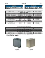
INSTALLATION OF 4” PLEATED PANEL
(PRE)FILTERS
These instructions are for installing 4" panel filters into type
8 holding frames.
• Latches needed for these applications are four (4) clips as
indicated in the table on page 30
.
• A single latch should be installed at each of the four (4)
corners of the frame.
• The latch fits into the set of knockouts, which consists of
two (2) rows of three (3) knockouts. The row of knockouts
closest to the gasketing should be used for filters with
a 13/16” single header in combination with a nominal 2”
prefilter. The second set of knockouts should be used for
nominal 4” filters.
Installation of Spring Latches
1. Insert the straight end of the latch between the two (2)
knockouts furthest from the corner.
2. Using a moderate amount of pressure, force the latch over
the third knockout.
Repeat the installation process with the remaining latches.
4. Insert the filter into the frame making sure that the pleats
are vertical.
5. After the filter has been placed into the frame, grasp the
loose end of the latch and place it over the filter frame, so
that the latch secures the filter into the frame.
Repeat for the remaining latches.
6. The filter should now be securely installed into the frame.
INSTALLATION OF SH SINGLE
HEADERED FILTERS
These instructions are for installing single-header rigid filters
into type 8 holding frames.
CAUTION
Care should be taken to prevent contamination of the
filter media prior to placement in the filter racks. Fresh
filters should never be placed on dirty surfaces such as
roofs or floors.
• Latches needed for these applications are four (4) clips as
indicated in the table on page 30
.
• A single latch should be installed at each of the four (4)
corners of the frame.
• The latch fits into the set of knockouts, which consists of
two (2) rows of three (3) knockouts
.
The row of knockouts
closest to the gasketing should be used for nominal 1”
filters or filters with a 13/16” single header. The second set
of knockouts should be used for nominal 2” filters.
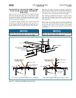
Installation of Latches
1. Insert the straight end of the latch between the two (2)
knockouts furthest from the corner.
2. Using a moderate amount of pressure, force the latch over
the third knockout
.
3. The latch installation should now be complete. The latch
should now be “trapped” within the three (3) knockouts, but
should be able to freely rotate
.
Repeat the installation process with the remaining latches.
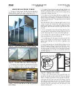
4. Rotate all of the latches outward, and insert the
SH filter
into the frame
.
The bulk of the filter should be inserted through
the frame, protruding out the backside. Only the header of
the filter should be contacting the flange of the frame.
5. After the filter has been placed into the frame, grasp the
circular end of the latch and rotate it across the corner of the
filter
.
Push the end of the latch towards the filter, until the latch
catches beneath the knockout on the frame.
Repeat for the remaining latches.
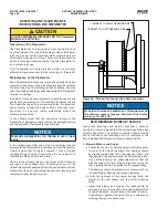
Figure 39 – Fully installed SH (single header) filter
6. The filter should now be securely installed into the frame
(see Figure 39).
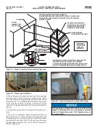
INSTALLATION OF A RIGID DH
DOUBLE-HEADERED FILTER
These instructions are for the installation of a Rigid DH Double-
Headered filter (nominal 12” deep double header) into a type
8 holding frame.
• The latches needed for this application are four (4) clips as
indicated in the table on page 30.
• Two latches should be attached on each side of the frame.
• The latches should only be installed, two (2) per side of
the frame. There should be no latches used on the top or
bottom. This is done to match the holes in the filter frame,
used to secure the latch to the filter. See Figure 40 for the
sets of knockouts that should be used for the latches.
Summary of Contents for AcuAir
Page 54: ......