


MPC563XM Reference Manual, Rev. 1
672
Freescale Semiconductor
Preliminary—Subject to Change Without Notice
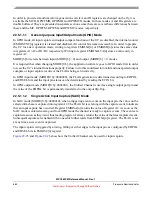
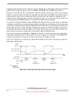
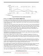
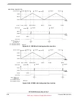
Figure 22-41. Quadrature Decode mode example with
count & direction
encoder
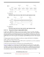
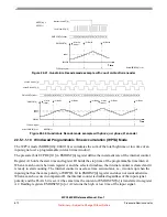
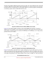
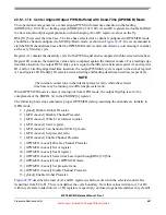
Figure 22-42. Quadrature Decode mode example with
phase_a & phase_B
encoder
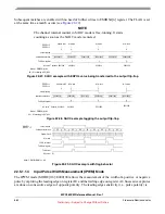
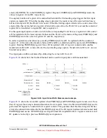
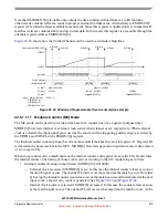
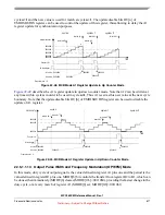
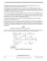
22.5.1.1.10
Windowed Programmable Time Accumulation (WPTA) Mode
The WPTA mode (MODE[0:6]=0001110) accumulates the sum of the total high time or low time of an
input signal over a programmable interval (time window).
The prescaler bits UCPRE[0:1] in EMIOSC[n] register define the increment rate of the internal counter.
Register A1 holds the start time and register B1 holds the stop time of the programmable time interval.
When a match occurs between register A and the selected timebase, the internal counter is cleared and it
is ready to start counting. The internal counter is used as a time accumulator, i.e., it counts up when the
input signal has the same polarity of EDPOL bit in EMIOSC[n] register and does not count otherwise.
When a match occurs in comparator B, the internal counter is disabled regardless of the input signal
polarity and the FLAG bit is set. At the same time the content of EMIOSCNT[n] is transferred to register
A2. Reading registers EMIOSCNT[n] or A2 returns the high or low time of the input signal,
Notes:
1. EMIOSA[n] => A1
+1 +1 +1 +1 +1 +1 +1
-1 -1 -1 -1 -1
EMIOSCNT[n] inc/dec
direction (from UC[n])
count (from UC[n-1])
$000000
EMIOSCNT[n]
Time
A1 write
A1 Match
FLAG pin/register
A1 Match
value 1
(value 1)
MODE
[6]
= 0
EDPOL = 1
+1
Notes:
1. EMIOSA[n] = A1
+1 +1 +1 +1 +1 +1 +1 +1
-1 -1 -1 -1 -1
+1 +1 +1 +1 +1 +1
-1
EMIOSCNT[n] inc/dec
phase A (from UC[n])
phase B (from UC[n-1])
$000000
EMIOSCNT[n]
Time
A1 write
A1 Match
FLAG pin/register
A1 Match
A1 Match
A1 Match
A1 Match
A1 write
value 2
value 1
(value 1)
(value 2)
MODE
[6]
= 1
-1
+1
+1
-1 -1 -1 -1 -1
+1 +1 +1 +1 +1 +1
-1
-1
+1


