


MPC5553/MPC5554 Microcontroller Reference Manual, Rev. 5
20-6
Freescale Semiconductor
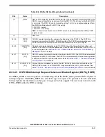
In slave mode, the SS signal is a slave select input signal that allows an SPI master to select the DSPI as
the target for transmission. PCS0/SS must be configured as input and pulled high. If the internal pull up is
being used then the appropriate bits in the relevant SIU_PCR must be set (SIU_PCR [WPE=1], [WPS=1]).
The IBE and OBE bits in the corresponding SIU_PCR need to be set appropriately for all PCSx0 pins when
the DSPI chip select/slave select primary function is selected for that pin. When the pin is to be used in
DSPI master mode as a chip select output, then the OBE bit should be set. When the pin is to be used in
DSPI slave mode as a slave select input, then the IBE bit should be set. See
Configuration Registers (SIU_PCR)
for more information.
20.2.2.2
Peripheral Chip Selects 1–3 (PCS[1:3])
PCS[1:3] are peripheral chip select output signals in master mode. In slave mode these signals are not used.
20.2.2.3
Peripheral Chip Select 4 / Master Trigger (PCS4/MTRIG)
PCS4 is a peripheral chip select output signal in master mode. In slave mode this signal is a master trigger.
20.2.2.4
Peripheral Chip Select 5 / Peripheral Chip Select Strobe (PCS5/PCSS)
PCS5 is a peripheral chip select output signal. When the DSPI is in master mode and PCSSE bit in the
DSPI
x
_MCR is negated, this signal is used to select which slave device the current transfer is intended for.
PCSS provides a strobe signal that can be used with an external logic device for deglitching of the PCS
signals. When the DSPI is in master mode and the PCSSE bit in the DSPI
x
_MCR is set, the PCSS provides
the appropriate timing for the decoding of the PCS[0:4] signals which prevents glitches from occurring.
PCS5/ PCSS is not used in slave mode.
20.2.2.5
Serial Input (SIN)
SIN is a serial data input signal.
20.2.2.6
Serial Output (SOUT)
SOUT is a serial data output signal.
20.2.2.7
Serial Clock (SCK)
SCK is a serial communication clock signal. In master mode, the DSPI generates the SCK. In slave mode,
SCK is an input from an external bus master.
20.3
Memory Map/Register Definition
20.3.1
Memory Map
shows the DSPI memory map.
Summary of Contents for MPC5553
Page 5: ...MPC5553 MPC5554 Microcontroller Reference Manual Rev 5 2 Freescale Semiconductor...
Page 21: ...MPC5553 MPC5554 Microcontroller Reference Manual Rev 5 xvi Freescale Semiconductor...
Page 47: ...MPC5553 MPC5554 Microcontroller Reference Manual Rev 5 1 26 Freescale Semiconductor...
Page 163: ...MPC5553 MPC5554 Microcontroller Reference Manual Rev 5 4 20 Freescale Semiconductor...
Page 179: ...MPC5553 MPC5554 Microcontroller Reference Manual Rev 5 5 16 Freescale Semiconductor...
Page 561: ...MPC5553 MPC5554 Microcontroller Reference Manual Rev 5 13 38 Freescale Semiconductor...
Page 615: ...MPC5553 MPC5554 Microcontroller Reference Manual Rev 5 14 54 Freescale Semiconductor...
Page 707: ...MPC5553 MPC5554 Microcontroller Reference Manual Rev 5 17 68 Freescale Semiconductor...
Page 755: ...MPC5553 MPC5554 Microcontroller Reference Manual Rev 5 18 48 Freescale Semiconductor...
Page 873: ...MPC5553 MPC5554 Microcontroller Reference Manual Rev 5 19 118 Freescale Semiconductor...
Page 984: ...MPC5553 MPC5554 Microcontroller Reference Manual Rev 5 Freescale Semiconductor 21 41...
Page 985: ...MPC5553 MPC5554 Microcontroller Reference Manual Rev 5 21 42 Freescale Semiconductor...
Page 1019: ...MPC5553 MPC5554 Microcontroller Reference Manual Rev 5 22 34 Freescale Semiconductor...
Page 1129: ...MPC5553 MPC5554 Microcontroller Reference Manual Rev 5 25 90 Freescale Semiconductor...


