


Clock Module
Freescale Semiconductor
8-9
8.3
Functional Description
This subsection provides a functional description of the clock module.
8.3.1
PLL Frequency Multiplication Factor Select
The frequency multiplication factor of the PLL is defined by the feedback divider and output dividers. An
example equation for the core frequency is given below:
Eqn. 8-7
where
f
sys
is the clock frequency of the ColdFire core and
f
REF
is the PLL clock source as shown in
. The allowable range of values for the PFDR is 4 to 34 and OUTDIV
n
is 1 to 15. However,
PFDR must also be selected such that the VCO frequency (
f
REF
PCR[PFDR]) is of the
range 300 – 540 MHz. The other clocks on the processor are configurable in a similar fashion. However,
there are various dependencies. See
Section 8.2.1, “PLL Control Register (PCR),”
for details.
The PCR[OUTDIV
n
] fields can be changed during normal operation or when the device is in limp mode.
However, PCR[PFDR] can only be altered during limp mode. After a new value is written to the PCR, the
PLL synchronizes the new value of the PCR with the VCO clock domain. Then, the transition from the old
divider value to the new divider value takes place, such that the PLL output clocks remain glitch free.
During the adjustment to the new divider value, a PLL output clock may experience an intermediate
transition while the divider values are being synchronized. Following the transition period, all output
clocks begin toggling at the new divider values simultaneously. The transition from the old divider value
to the new divider value takes no more than 100 ns. Because the output divider transition takes a period of
time to change, the PCR may not be written back-to-back without waiting 100 ns between writes.
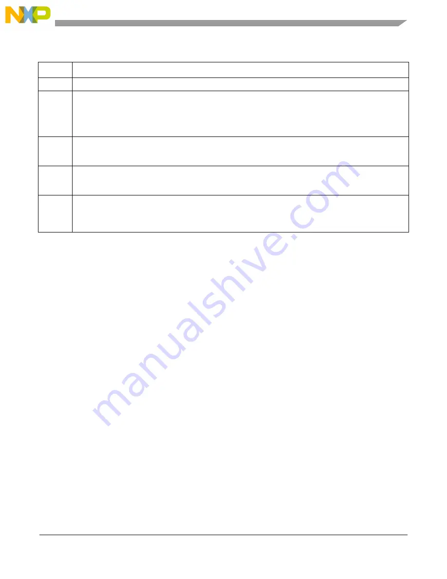
Table 8-4. PSR Field Descriptions
Field
Description
31–4
Reserved, must be cleared.
3
LOLRE
PLL loss of lock reset enable. Because reset clears the PSR register, if this bit is set and a loss-of-lock occurs, the
user must read the reset status register (RSR) to determine a loss-of-lock condition occurred. See
for more details on RSR.
0 Loss of lock does not generate a reset.
1 Loss of lock generates a reset to the device.
2
LOLIRQ
PLL loss-of-lock interrupt enable. Enables an interrupt request to generate when the PLL loses lock.
0 Loss-of-lock does not generate an interrupt request.
1 Loss-of-lock generates an interrupt request.
1
LOCK
PLL lock status. Indicates a locked PLL. See
Section 8.3.2, “Lock Conditions,”
for more details.
0 PLL is not locked.
1 PLL is locked.
0
LOCKS
PLL lost lock. Indicates that the PLL has lost lock. If the PFDR field changes or if an unexpected loss-of-lock condition
occurs, this bit is set. This bit is sticky and the user must clear it before the PLL can write the register again.
0 PLL has not lost lock.
1 PLL has lost lock.
f
SYS
f
REF
PCR PFDR
PCR OUTDIV1
1
+
------------------------------------------------------
=
Summary of Contents for MCF54455
Page 33: ...xxviii Freescale Semiconductor ...
Page 67: ...Freescale Semiconductor 1 ...
Page 125: ...Freescale Semiconductor 1 ...
Page 145: ...Enhanced Multiply Accumulate Unit EMAC 5 21 Freescale Semiconductor ...
Page 173: ...Cache 6 28 Freescale Semiconductor ...
Page 179: ...Static RAM SRAM 7 6 Freescale Semiconductor ...
Page 207: ...Power Management 9 16 Freescale Semiconductor ...
Page 323: ...Reset Controller Module 13 8 Freescale Semiconductor ...
Page 389: ...Pin Multiplexing and Control 16 44 Freescale Semiconductor ...
Page 575: ...PCI Bus Controller 22 58 Freescale Semiconductor ...
Page 600: ...Advanced Technology Attachment ATA Freescale Semiconductor 23 25 ...
Page 601: ...Freescale Semiconductor 1 ...
Page 842: ...I2 C Interface Freescale Semiconductor 33 16 ...
Page 843: ...Freescale Semiconductor 1 ...
Page 921: ...Revision History A 6 Freescale Semiconductor ...


