


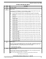


LPTMRx_CSR field descriptions (continued)
Field
Description
01
Pulse counter input 1 is selected.
10
Pulse counter input 2 is selected.
11
Pulse counter input 3 is selected.
3
TPP
Timer Pin Polarity
Configures the polarity of the input source in Pulse Counter mode. TPP must be changed only when the
LPTMR is disabled.
0
Pulse Counter input source is active-high, and the CNR will increment on the rising-edge.
1
Pulse Counter input source is active-low, and the CNR will increment on the falling-edge.
2
TFC
Timer Free-Running Counter
When clear, TFC configures the CNR to reset whenever TCF is set. When set, TFC configures the CNR to
reset on overflow. TFC must be altered only when the LPTMR is disabled.
0
CNR is reset whenever TCF is set.
1
CNR is reset on overflow.
1
TMS
Timer Mode Select
Configures the mode of the LPTMR. TMS must be altered only when the LPTMR is disabled.
0
Time Counter mode.
1
Pulse Counter mode.
0
TEN
Timer Enable
When TEN is clear, it resets the LPTMR internal logic, including the CNR and TCF. When TEN is set, the
LPTMR is enabled. While writing 1 to this field, CSR[5:1] must not be altered.
0
LPTMR is disabled and internal logic is reset.
1
LPTMR is enabled.
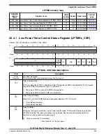
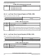
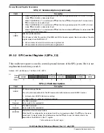
28.3.2 Low Power Timer Prescale Register (LPTMRx_PSR)
Address: 4004_0000h base + 4h offset = 4004_0004h
Bit
31
30
29
28
27
26
25
24
23
22
21
20
19
18
17
16
R
W
Reset
0
0
0
0
0
0
0
0
0
0
0
0
0
0
0
0
Bit
15
14
13
12
11
10
9
8
7
6
5
4
3
2
1
0
R
W
Reset
0
0
0
0
0
0
0
0
0
0
0
0
0
0
0
0
Memory map and register definition
KL02 Sub-Family Reference Manual, Rev. 2.1, July 2013
436
Freescale Semiconductor, Inc.


