background image

© Freescale Semiconductor, Inc., 2004. All rights reserved.


Freescale Semiconductor

Quick Start Guide

Rev. 0.1, 06/29/2004

EVB9S12NE64 Demo 

Quick Start Guide

Introduction and Default Settings

This kit and guide contains everything you need to get started. You will connect the board to your PC, run 
the pre-programmed Startup Demo, install the correct version of CodeWarrior, and load and play the 
demo game, called “The Connector.” Source code for both demos and the Serial Monitor are provided on 
the MC9S12NE64 Resource CD. 

Figure 1

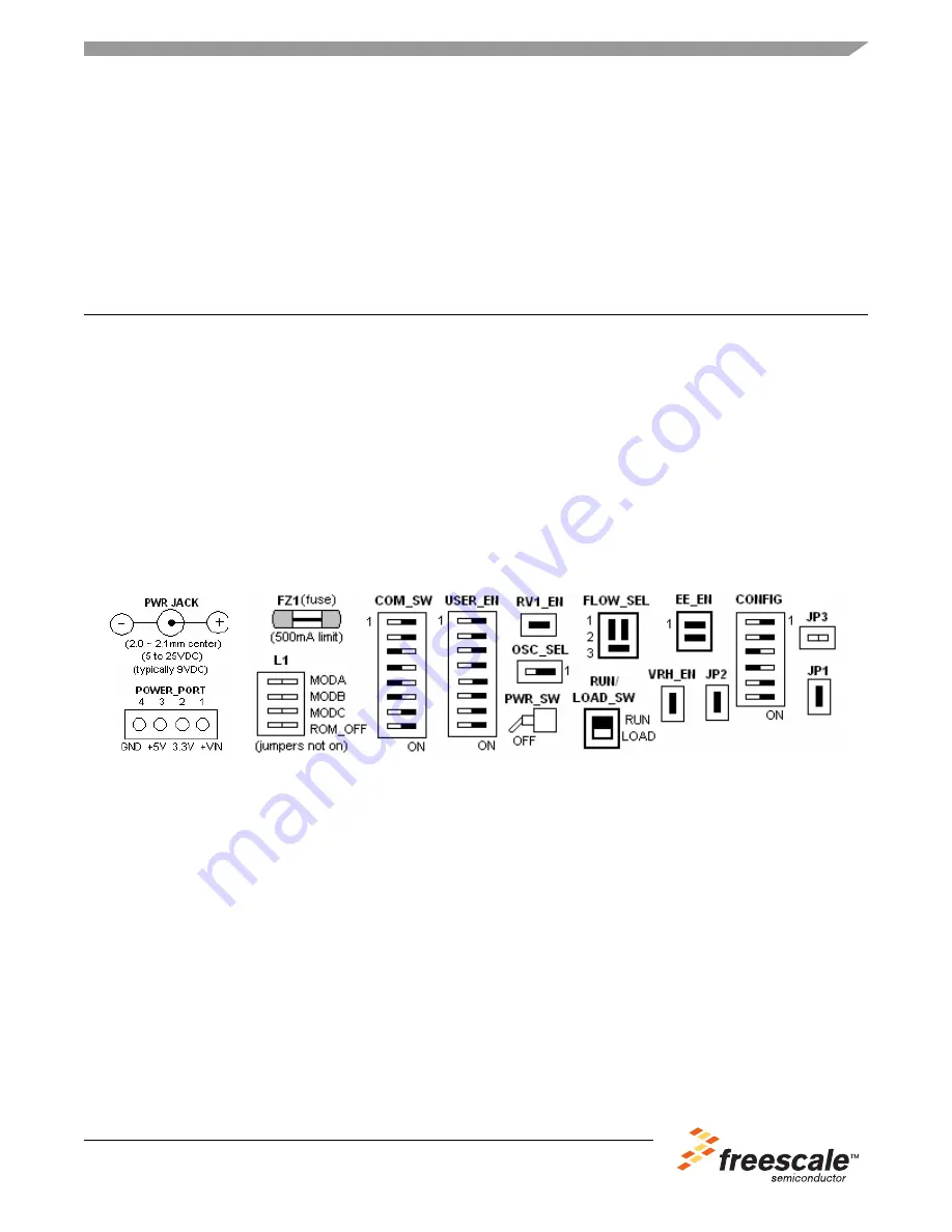
 contains diagrams of the power jack and port, the fuse (FZ1), 

and all default settings of the EVB9S12NE64 evaluation board. These settings are necessary for the 
pre-programmed Startup Demo to work properly. Please refer to the EVB9S12NE64 User's Guide on the 
MC9S12NE64 Resource CD provided for information on other configurations, other ports, etc. Black 
blocks indicate “on” positions of jumpers or switches. All diagrams in this guide are oriented with the PWR 
JACK, in the upper left hand corner. All other ports are open (no jumpers). The board comes with the 
default settings already set. You may check the settings or continue. 

Figure 1. Default Settings for EVB9S12NE64

Connect the EVB9S12NE64 to your computer and apply power

1.

Connect one end of the Crossover Ethernet cable provided to the J1 Ethernet Connector of the 
EVB board. Connect the other end to the Ethernet port of your host PC.

2.

Connect the 9-pin serial cable provided to the COM1 port of the EVB board. Connect the other end 
to a COM port on your host PC.

3.

There are two ways to apply power to the EVB: via the power jack or the power port. Refer to the 
EVB9S12NE64 User's Guide about using the power port. Otherwise, plug the wall plug power 
supply provided into a power outlet and install the barrel connector into the PWR JACK on the EVB 
board. If you are not using the original adapter supplied, please refer to the specs in the diagram 
above for the PWR JACK.

4.

Set the EVB board RUN/LOAD switch to the RUN position.

5.

Turn the PWR_SW switch ON. The +V, +3.3V, and +5V LEDs should come on. Either LED1 or 
LED2 (not both) should turn on as well, indicating that you are in Test1 of the Startup Demo.

Summary of Contents for EVB9S12NE64

Page 1: ...n the upper left hand corner All other ports are open no jumpers The board comes with the default settings already set You may check the settings or continue Figure 1 Default Settings for EVB9S12NE64 Connect the EVB9S12NE64 to your computer and apply power 1 Connect one end of the Crossover Ethernet cable provided to the J1 Ethernet Connector of the EVB board Connect the other end to the Ethernet ...

Page 2: ...ify that the PC is communicating with the EVB board through the Ethernet Crossover cable provided in the kit but you must first set the PC s IP address to one that is compatible with the board s IP address For this demo you will set the PC s IP address to 192 168 2 1 The board s IP address is currently set at 192 168 2 3 The mask for both should be 255 255 255 0 1 Board s IP address The board s IP...

Page 3: ... be established see Reasons Why the Ping Test might fail Install CodeWarrior Development Studio Version 3 1 for HC S 12 If you do not have Version 3 1 of CodeWarrior for HC S 12 installed on your computer please refer to the provided CodeWarrior Development Studio for Motorola CD for HC S 12 Special Edition Version 3 1 and the included CodeWarrior Quick Start Important You must register and obtain...

Page 4: ...l code change ex type a space then Del and retry 7 Assure the RUN LOAD_SW is set to LOAD and then press and release the RESET button on the EVB board 8 Click on Debug under Project in the menu bar or hit F5 The True Time Simulator Real Time Debugger should initiate serial communications with the EVB board As soon as the debugger opens the code currently in the MC9S12NE64 s Flash memory is erased a...

Page 5: ...lish a connection press the RESET button on the EVB board and retry The COM port on the PC may be in use by another application If so disconnect that application or connection RUN LOAD_SW may not be in the correct position LOAD to Flash memory and RUN to run program Please check your steps Reasons Why the Ping Test might fail Ethernet cable may not be secure IP addresses or masks may not be set co...

Page 6: ...ges Typical parameters which may be provided in Freescale Semiconductor data sheets and or specifications can and do vary in different applications and actual performance may vary over time All operating parameters including Typicals must be validated for each customer application by customer s technical experts Freescale Semiconductor does not convey any license under its patent rights nor the ri...

Reviews: