background image

DFA400 Rev0708

11

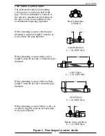
Figure 3.  Flow Sensor Location  Guide

Flow Sensor Location Guide

The preferred location for mounting 

a flow sensor is on the top half of the 

pipe. The best orientation is vertical. If 

the sensor is mounted on the bottom of 

the pipe, it may be susceptible to dirt 

accumulation impacting operation. 

When mounting a sensor after the pipe 

diameter is reduced, length L must be at 

least 2 times the pipe diameter.

When mounting a sensor after a valve, 

length L must be at least 14 times the pipe 

diameter.

When mounting a sensor after an elbow, 

length L must be at least 6 times the pipe 

diameter.

When mounting a sensor before a valve or 

an elbow, length L must be at least equal 

to the pipe diameter.

Before Valve or Elbow

L > 1 X PIPE DIA.

After Elbow

L > 6 X PIPE DIA.

After Valve

L > 14 X PIPE DIA.

After Reduction

L > 2 X PIPE DIA.

Best Orientation 

is Vertical

L

L

L

L

Summary of Contents for DFA400

Page 1: ...ev0708 1 FIRE RESEARCH CORPORATION www reresearch com 26 Southern Blvd Nesconset NY11767 TEL 631 724 8888 FAX 631 360 9727 TOLL FREE 1 800 645 0074 DIGITAL FLOWMETER MODEL DFA400 Document Number XE DF...

Page 2: ...8 Install Display Module 8 Install Flow Sensor 10 OPERATION 16 Datalink Interface 16 Program Features 17 TOTAL Button 17 PROGRAMMING 18 Inputs 18 Display Module Identi cation Mode 18 Program Access M...

Page 3: ...List of Figures Figure 1 Controls and Indicators 7 Figure 2 Display Module Mounting Dimensions 8 Figure 3 Flow Sensor Location Guide 11 Figure 4 Saddle Clamp Installation 13 Figure 5 Weldment Installa...

Page 4: ...processed and shown on the digital display There are two operator selectable modes display module identi cation and program access In the display module identi cation mode the digital display shows th...

Page 5: ...Module SupplyVoltage 9 to 30 VDC Current 1 5 Amps Maximum Dimensions Height 3 1 4 Width 3 1 4 Depth 2 Flow Sensor Model Number XE MF15P Type Paddlewheel Sensor Material Acetal Delrin with Stainless St...

Page 6: ...ocated on the front of the display module Refer to Controls and Indicators Paddlewheel Flow Sensor The ow sensor provides an input signal to the display module proportional to discharge ow rate It is...

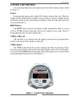
Page 7: ...on The MODE button accesses the display module identi cation mode It is used with the TOTAL button to input data when in the program access mode Refer to Programming Section for more information TOTAL...

Page 8: ...d mark mounting location for display module panel cutout and mounting screw holes Make sure there is clearance behind the panel for the display and cables before cutting holes Refer to Figure 2 for la...

Page 9: ...DFA400 Rev0708 9 This page intentionally left blank...

Page 10: ...stream to stabilize into a uniform ow Guidelines for selecting ow sensor locations are outlined in Figure 3 Turbulent Water When the ow sensor is mounted after an area in the plumbing that tends to in...

Page 11: ...after the pipe diameter is reduced length L must be at least 2 times the pipe diameter When mounting a sensor after a valve length L must be at least 14 times the pipe diameter When mounting a sensor...

Page 12: ...osition It is not meant to be removed 3 Place saddle clamp over hole with sensor housing centered 4 Tighten saddle clamp nuts until gasket makes a tight seal 5 Insert ow sensor into sensor housing Ali...

Page 13: ...e sure the ow sensor engages the alignment tab and does not rotate Note Dimensions are typical and are an aid to determine ow sensor mounting locations Pipe Size Dimensions Sch 40 A B C 2 5 5 3 9 2 9...

Page 14: ...the pipe centerline Refer to Figure 5 4 Set sensor housing to dimension A in Figure 5 Make sure alignment tab is centered on the pipe as shown it can be on upstream or downstream side 5 Install tru s...

Page 15: ...ke sure the ow sensor engages the alignment tab and does not rotate Note Allow a minimum of 2 inches clearance above the sensor for connector removal installation Make sure that the alignment tab is c...

Page 16: ...datalink When programmed with Id 1 to Id 99 it provides information via the datalink to remote summing and accumulator displays Remote Display Module Remote displays are programmed with the module fu...

Page 17: ...harge or reset the totalized ow value to 0 if totalizer reset function is set to YES Display Total Flow When the TOTAL button is pressed and released the digital display shows the total accumulated ow...

Page 18: ...changes the digit or option choice Display Module Identi cation Mode When in the module identi cation mode the digital display shows the module serial number manufactured date software revision funct...

Page 19: ...ssed the number increments by 1 Set the rst digit to the desired number 3 Press the TOTAL button The second digit ashes Each time the TOTAL button is pressed the number increments by 1 Set the second...

Page 20: ...ltiple Point 9 Calibration Points 340 CAN Terminator On Off E202 Invalid Program Code Entered Re Enter Code E204 No Flow Sensor Signal Check Water Flow and Wiring E206 Invalid Calibration Point Select...

Page 21: ...DFA400 Rev0708 21 This page intentionally left blank...

Page 22: ...Options 0 to 99 This code sets the datalink identi cation ID number for the display module The display is programmed with an ID number between 0 and 99 When a display module is programmed with Id 0 no...

Page 23: ...inues to accumulate and does not reset to 0 even when power is removed Code 318 Flow Cutoff Frequency Factory programmed value c 30 Options 0 to 99 9 Hz This code sets a cutoff frequency for the ow se...

Page 24: ...ctory programmed value No Values Entered Options 9 Calibration Points This code starts the calibration program for multiple ow rates This function is used when the ow sensor is installed in a dif cult...

Page 25: ...less than 5 difference between two calibration points Select a different point to continue with the calibration procedure Error Code E208 There is a failure with the internal memory of the module Cont...

Page 26: ...le Point Code 321 Select a ow rate for calibration that is within the most commonly used discharge ow range 1 Enter code 321 Result The digital display shows ow rate with the last digit ashing 2 Flow...

Page 27: ...ure a constant pressure is maintained to obtain a steady ow rate 3 Press the MODE button Result The display shows ow rate with the last digit ashing 4 Adjust the displayed ow rate to match the referen...

Page 28: ...and the datalink connection pins 7 and 8 to the primary display A remote display must be programmed with the same ID number as the primary display Figure 6 Display Module Wiring 8 Pin Connector Cable...

Page 29: ...nsor Figure 7 Flow Sensor Wiring Sensor Cable 3 Pin Connector Pin Wire Description A Black Ground B Red Supply Voltage C White Signal Signal Output Supply Voltage Ground Sensor Cable from 8 Pin Connec...

Reviews: