FRC AUTOFOAM FSA015 Manual Download Page 1

FSA100 Rev1206

1

FIRE RESEARCH CORPORATION

www.fireresearch.com

26 Southern Blvd., Nesconset, NY11767

TEL  ( 631 ) 724-8888  FAX  ( 631 ) 360-9727  

TOLL  FREE  1-800-645-0074
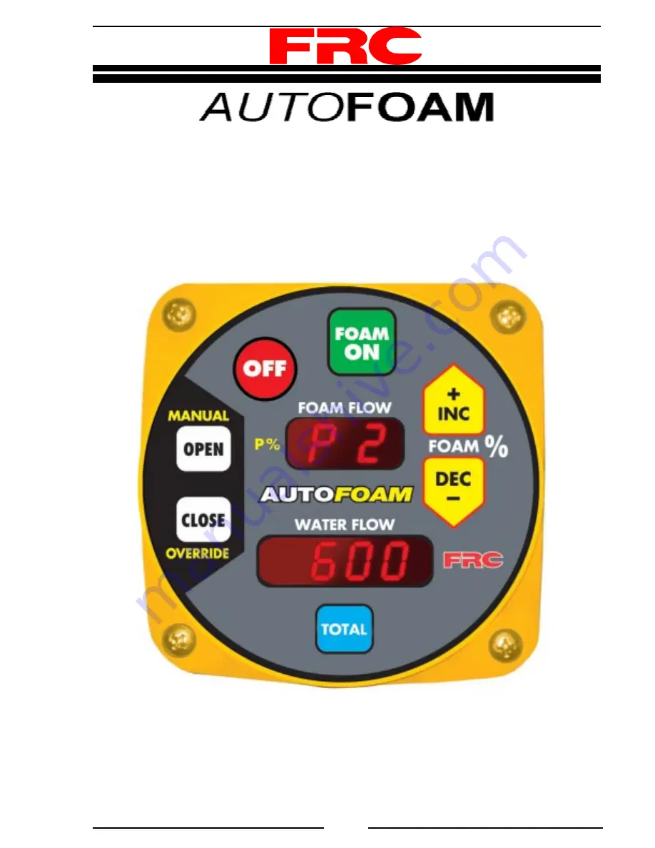
AUTOMATIC

AROUND-THE-PUMP

FOAM SYSTEM

MODELS: FSA015, FSA030, FSA060, FSA120

Document Number:
XE-FSA0PM-R0A

Summary of Contents for AUTOFOAM FSA015

Page 1: ...CORPORATION www fireresearch com 26 Southern Blvd Nesconset NY11767 TEL 631 724 8888 FAX 631 360 9727 TOLL FREE 1 800 645 0074 AUTOMATIC AROUND THE PUMP FOAM SYSTEM MODELS FSA015 FSA030 FSA060 FSA120...

Page 2: ...Discharge Pressure Requirements 23 Operational Check 24 CALIBRATION 28 TROUBLESHOOTING TIPS 30 MAINTENANCE 31 Flushing the System 31 Cleaning the Paddlewheel Sensors 31 DRAWINGS 32 List of Figures Ta...

Page 3: ...d between the water pump intake and pump discharge A small flow of water from the pump discharge passes through the eductor and creates a vacuum that draws foam concentrate into the eductor The princi...

Page 4: ...w Rate All Systems 3000 GPM Dependent on Foam Solution Proportioning Ratio FSA120 1 10 FSA060 0 5 6 FSA030 0 5 6 FSA015 0 5 6 Control Module Power 12 VDC Nominal Logic 8 BIT Microcontroller Housing Pa...

Page 5: ...Material Stainless Steel 304 Weight 4 2 LBS FSA120 Length FSA120 20 FSA060 12 5 FSA030 12 5 FSA015 12 5 Water Flow Rate Through Eductor 150 PSI FSA120 205 GPM FSA060 130 GPM FSA030 130 PM FSA015 50 GP...

Page 6: ...is internally calibrated for flow The meter valve housing is brass The flow sensors are in stainless steel mounts Eductor The eductor is located in a water by pass loop and foam is sucked through it...

Page 7: ...Foam Tank EDUCTOR Pump Pump Suction Pump Discharge Power 12 VDC Foam Isolating Valve METERING VALVE with DUAL FOAM FLOW SENSORS Flush Valve Emergency Manual Bypass Valve DISCHARGE FLOW SENSOR CONTROL...

Page 8: ...o back to show foam flow FOAM Buttons Press these buttons to raise or lower the percent of foam that is inducted When the increase or decrease button is pressed the upper display will show the selecte...

Page 9: ...nd Indicators Manual OVERRIDE Buttons OFF Button FOAM ON Button Increase Foam Percent Button Decrease Foam Percent Button Upper Display Lower Display TOTAL Button FOAM ON OFF FOAM 0PEN CLOSE OVERRIDE...

Page 10: ...e eductor be mounted below the bottom of the foam tank Note The metering valve assembly must be mounted so that the motor assembly is on top 1 Connect the pump discharge to the eductor inlet A Reinfor...

Page 11: ...and Eductor Installation Interconnecting pipe diameters FSA120 system 2 0 FSA015 030 060 system 1 5 Valve motor assembly must be on top MeteringValve Assembly Pump Suction From Foam Tank Pump Discharg...

Page 12: ...r or smooth to ensure accurate flow measurements There must be enough straight pipe run before the flow sensor location to allow the water stream to stabilize into a uniform flow Guidelines for select...

Page 13: ...ipe diameter When mounting the sensor before a valve or an elbow the length L must be at least equal to the pipe diameter When mounting the sensor after the pipe diameter is reduced the length L must...

Page 14: ...ect position and is not meant to be removed 3 Place saddle clamp over hole with sensor housing centered 4 Tighten saddle clamp nuts until gasket makes a good tight seal 5 Insert flow sensor into senso...

Page 15: ...for removal installation of the connector Note When the retainer cap is tightened make sure the sensor rim flat spot does not disengage from the alignment tab and allow the flow sensor to rotate Pipe...

Page 16: ...t tab is centered on the pipe centerline Refer to Figure 7 4 Set sensor housing to dimension A in Figure 7 Make sure the alignment tab is centered on the pipe as shown it can be on upstream or downstr...

Page 17: ...e in inches Note These dimensions are typical and are given to be used as an aid in determining mounting locations for flow sensors Make sure that the alignment tab is centered on the pipe centerline...

Page 18: ...re to ground 2 Connect two 2 foam flow sensors to the summing device with the extension cables supplied 3 Connect the discharge flow sensor to the summing device with the extension cable supplied For...

Page 19: ...Black Wire GND Power Metering Valve and Dual Flow Sensors AUTOFOAM Summing Box Metering Valve Multiple Discharge Flow Sensor Option Discharge Flow Sensor Y Cable AutoFoam Summing Device Discharge Flo...

Page 20: ...he selected foam proportion If input data from one of the dual foam concentrate flow sensors is lost the program will automatically use the information from the one that is operating properly There is...

Page 21: ...des feedback on the valve position The valve position is directly related to how much foam concentrate flows The program uses the selected foam proportion percent and the discharge water flow rate to...

Page 22: ...utton Result After 3 seconds the display shows 0 6 Press and hold decrease Foam button Result Upper display shows P on left and decreasing number on right 7 Release decrease Foam button Result After 3...

Page 23: ...ge pressure to more than 140 PSI when foam is used For efficient operation around the pump foam proportioning systems require a pump intake to discharge pressure differential It is recommended that th...

Page 24: ...injected if water is flowing through the pump Set the desired foam proportion percent When the FOAM button is pressed the upper display will show the selected percent for 3 seconds then show foam conc...

Page 25: ...off Upper display shows OFF Lower display is blank or if pump is running shows water flow at discharge sensor AutoFoam system is on Upper display shows selected P on left side indicates selected is di...

Page 26: ...m is in Automatic mode Upper display shows foam concentrate flow Lower display shows discharge flow AutoFoam system is on System is in Fixed Program mode Upper display flashes showing F alternating wi...

Page 27: ...system is on TOTAL button is pressed and held Upper display x 1 shows the total gallons of foam concentrate used Lower display x 100 shows the total gallons of water used Note The number in lower disp...

Page 28: ...ase the flow rate and counter clockwise will decrease the flow rate Turn the pot a little bit at a time to allow the computer averaging to catch up to the new setting wait for two seconds between adju...

Page 29: ...ocknut on the correct foam flow calibration potentiometer pot Use a small screwdriver to adjust the pot so that the reading in the upper display on the control module matches the reference flow Rotati...

Page 30: ...nd the control module Perform the Operational Check 1 If this check fails step 4 with discharge flow the possible problems are Wiring to the discharge flow sensor Wiring between the control module and...

Page 31: ...d foam isolating valves are closed Open the flush valve and the eductor water valve if installed 3 Press FOAM ON button 4 Open discharge and pump water 5 Press and hold Manual OVERRIDE OPEN button Run...

Page 32: ...FSA100 Rev1206 32 Figure 11A Eductor Drawing DRAWINGS F F 1 5 2 0 1 9 2 375 Dimensions in Inches Linear Dimensions are 0 040 10 4 8 650 F FSA015 030 060 FSA120 FSA015 FSA030 FSA060 FSA120...

Page 33: ...FSA100 Rev1206 33 Figure 11B Metering Valve Drawing A Grooved Type Coupling FSA015 1 9 1 5 pipe FSA060 1 9 1 5 pipe FSA030 1 9 1 5 pipe FSA120 2 375 2 0 pipe 16 25 to 17 25 6 15 8 43 6 72 A A...

Reviews: