aPbox Installation and Operations Manual
18
Wiring
Make AC power connections
Use copper wires rated at 167°F (75°C) or 194°F (90°C), depending on the requirements.
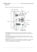
Connect the grid (or an equivalent AC power source) conductors to the TB1 terminal, and
the PV conductors to the TB2 terminal.
Refer to
Table 1 aPbox Power Wiring
below for wiring requirements including wire gauges,
torques and strip lengths.
Table 1: aPbox Power Wiring
Terminal
Wire Gauge (Copper)
Torque Lb*In (N*m)
Strip Length In (mm)
TB1
3AWG max.
30.1 (3.5)
0.6 (16)
TB2
3AWG max.
30.1 (3.5)
0.6 (16)
TB3
16-20AWG
4.5 (0.5)
0.28 (7)
DANGER
Before wiring, check that all circuits to be connected to the aPbox are completely
de-energized, and lock out any associated circuits breakers and disconnect
switches.
NOTE
•
TB1 must be connected to the grid or an equivalent 240 Volt, 60Hz AC
power source.
•
TB2 must be connected to the PV system(s). TB2 supports up to two
PV system connections.
•
Incorrect wiring of AC power conductors presents a risk of electrical
shock or damage to equipment. Before connecting power, ensure all
connections are made according to the instructions in this document
and in accordance with all local wiring codes and regulations.
•
Always connect an aPbox with two phase wires, one neutral, one
ground.
•
Protection devices, such as circuit breakers and fuses, should be
installed upstream of the TB1, the amperage of which should be
depending on the site requirements and in accordance with NEC and
local codes and regulations.
•
Cut and strip the wires outside the aPbox enclosure and make sure no
copper wires or powder remain in the box.


