background image

!

35!

responsible for compliance could void the user's authority to operate this equipment. 
This transmitter must not be co-located or operating in conjunction with any other 
antenna or transmitter. 

!

Operations in the 5.15-5.25GHz band are restricted to indoor usage only.   

Radiation Exposure Statement: 

This equipment complies with FCC radiation exposure limits set forth for an 
uncontrolled environment. This equipment should be installed and operated with 
minimum distance 20cm between the radiator & your body. 

This device is intended only for OEM integrators under the following conditions: 

1) The antenna must be installed such that 20 cm is maintained between the antenna 
and users, and 2) The transmitter module may not be co-located with any other transmitter 
or antenna. 
As long as 2 conditions above are met, further transmitter test will not be required. 
However, the OEM integrator is still responsible for testing their end-product for any 
additional compliance requirements required with this module installed 

IMPORTANT NOTE: 

In the event that these conditions can not be met (for example 

certain laptop configurations or co-location with another transmitter), then the FCC 
authorization is no longer considered valid and the FCC ID can not be used on the 
final product. In these circumstances, the OEM integrator will be responsible for 
reevaluating
the end product (including the transmitter) and obtaining a separate FCC 
authorization.

End Product Labeling 

This transmitter module is authorized only for use in device where the antenna may be 
installed such that 20 cm may be maintained between the antenna and users. The 
final end product must be labeled in a visible area with the following: “Contains FCC 
ID: MCLJ20H081”. The grantee's FCC ID can be used only when all FCC compliance 
requirements are met. 

Manual Information To the End User 

The OEM integrator has to be aware not to provide information to the end user 
regarding how to install or remove this RF module in the user’s manual of the end 
product which integrates this module. 
The end user manual shall include all required regulatory information/warning as show 
in this manual. 

For Taiwan 

ᤞ፿Κ!

(

ሽॾጥࠫ୴᙮ᕴޗࠌش

)

ᆖীڤᎁᢞٽ௑հ܅פ෷୴᙮ሽᖲΔॺᆖ๺ױΔֆ׹Ε೸ᇆࢨࠌشृ݁լ൓ᖐ۞᧢ޓ᙮!
෷ΕףՕפ෷ࢨ᧢ޓ଺๻ૠհ௽ࢤ֗פ౨Ζ!
܅פ෷୴᙮ሽᖲհࠌشլ൓ᐙ᥼ଆ౰ڜ٤֗եឫٽऄຏॾΙᆖ࿇෼ڶեឫ෼ွழΔᚨم!
ܛೖشΔࠀޏ࿳۟ྤեឫழֱ൓ᤉᥛࠌشΖছႈٽऄຏॾΔਐࠉሽॾऄ๵ࡳ܂ᄐհྤᒵ!
ሽຏॾΖ܅פ෷୴᙮ሽᖲႊݴ࠹ٽऄຏॾࢨՠᄐΕઝᖂ֗᠔᛭شሽंᘿ୴ࢤሽᖲ๻ໂհ!
եឫΖ!

Note: 1. 

ءᑓิ࣍࠷൓ᎁᢞ৵ലࠉ๵ࡳ࣍ᑓิء᧯ᑑقᐉ᧭ٽ௑ᑑ᧘!

2.

ߓอᐗ೸ᚨ࣍ؓ!

؀Ղᑑقψءข঴փܶ୴᙮ᑓิ

: XXXyyyLPDzzzz-x (NCC ID) 

ωڗᑌ!

!
!

Summary of Contents for J20H081

Page 1: ...Foxconn Part No J20H081 00 Prepared by Reviewed by Approved by Clon Liu Eddie Huang Ambit Microsystems Shanghai LTD No 1925 Nanle Road Songjiang Export Processing Zone Shanghai China Tel 86 21 6120668...

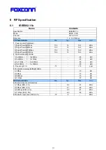
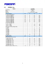
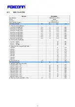
Page 2: ...AXIMUM RATING 9 5 2 RECOMMENDED OPERATING RATING 9 5 3 DC CHARACTERISTICS 9 5 4 ESD INFORMATION 9 5 5 ENVIRONMENT STORAGE CONDITION 9 6 RF SPECIFICATION 21 6 1 IEEE802 11B 21 6 2 IEEE802 11G 22 6 3 80...

Page 3: ...nt revision Change Description 2013 08 31 1 0 Initial release 2013 10 14 1 1 Add BT specification and modify Wifi specification 2013 10 15 1 2 Modify BT standard from V3 0 HS standard to V3 0 standard...

Page 4: ...5 2 Manufacturing Information Manufacture Country Made in China Manufacturer Ambit Microsystems Shanghai LTD Manufacture Address No 1925 Nanle Road Songjiang Export Processing Zone Shanghai China...

Page 5: ...ing accelerators which offloads the host processor 3 1 Application scope The wireless LAN is compliant to IEEE 802 11n IEEE 802 11 a b g and IEEE 802 11 ac standards The data rate of 802 11b is up to...

Page 6: ...02 11a b g n ac 1X1 based on MTK MT7650U solution i Support BT3 0 i USB 2 0 Interface High and Full Speeds supported i Module is powered by the host with a 5 0V 5 supply i External PCB printed antenna...

Page 7: ...8 Pin Number Symbol Name Status Pin definition 1 GND Ground 2 DP I O USB positive data 3 DM I O USB negative data 4 UV P USB 5V power input 5 GND Ground S1 GND Ground S2 GND Ground...

Page 8: ...2 4GHz Tx Current 11M 15dBm mA 2 4GHz Tx Current 6M 15dBm mA 2 4GHz Tx Current 54M 15dBm 220 mA 2 4GHz Tx Current MCS0 15Bm HT20 220 mA 2 4GHz Tx Current MCS7 15dBm HT20 220 mA Rx Current 80 mA 5GHz T...

Page 9: ...Environment condition Temperature Operating Temperature 10 deg C 70 deg C Storage Temperature 40 deg C 85 deg C Humidity Operating Humidity 20 90 Storage Humidity 20 90...

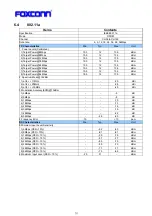
Page 10: ...6 5 dBm 4 Target Power 11Mbps 13 5 15 16 5 dBm 2 Spectrum Mask 15dBm 1 fc 33MHz f fc 22MHz 50 dBr 2 fc 22MHz f fc 11MHz 30 dBr 3 fc 11MHz f fc 22MHz 30 dBr 4 fc 22MHz f fc 33MHz 50 dBr 3 Frequency Err...

Page 11: ...bps 13 5 15 16 5 dBm 8 Target Power 54Mbps 13 5 15 16 5 dBm 2 Spectrum Mask 15dBm 1 at fc 11MHz 20 dBr 2 at fc 20MHz 28 dBr 3 at fc 30MHz 40 dBr 3 Modulation Accuracy EVM 15dBm 1 6Mbps 5 dB 2 9Mbps 8...

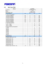
Page 12: ...Target Power MCS6 13 5 15 16 5 dBm 8 Target Power MCS7 13 5 15 16 5 dBm 2 Spectrum Mask 15dBm 1 at fc 11MHz 20 dBr 2 at fc 20MHz 28 dBr 3 at fc 30MHz 45 dBr 3 Modulation Accuracy EVM 15dBm 1 MCS0 5 d...

Page 13: ...wer MCS6 12 5 14 15 5 dBm 8 Target Power MCS7 12 5 14 15 5 dBm 2 Spectrum Mask 15dBm 1 at fc 11MHz 20 dBr 2 at fc 20MHz 28 dBr 3 at fc 30MHz 45 dBr 3 Modulation Accuracy EVM 15dBm 1 MCS0 5 dB 2 MCS1 1...

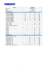
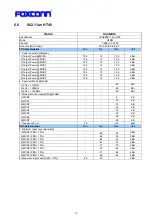
Page 14: ...ps 10 5 12 13 5 dBm 8 Target Power 54Mbps 10 5 12 13 5 dBm 2 Spectrum Mask 12dBm 1 at fc 11MHz 20 dBr 2 at fc 20MHz 28 dBr 3 at fc 30MHz 40 dBr 3 Modulation Accuracy EVM 15dBm 1 6Mbps 5 dB 2 9Mbps 8 d...

Page 15: ...7 Target Power MCS6 10 5 12 13 5 dBm 8 Target Power MCS7 10 5 12 13 5 dBm 2 Spectrum Mask 15dBm 1 at fc 11MHz 20 dBr 2 at fc 20MHz 28 dBr 3 at fc 30MHz 45 dBr 3 Modulation Accuracy EVM 15dBm 1 MCS0 5...

Page 16: ...7 Target Power MCS6 10 5 12 13 5 dBm 8 Target Power MCS7 10 5 12 13 5 dBm 2 Spectrum Mask 15dBm 1 at fc 11MHz 20 dBr 2 at fc 20MHz 28 dBr 3 at fc 30MHz 45 dBr 3 Modulation Accuracy EVM 15dBm 1 MCS0 5...

Page 17: ...11 12 5 dBm 8 Target Power MCS7 9 5 11 12 5 dBm 2 Spectrum Mask 15dBm 1 at fc 11MHz 20 dBr 2 at fc 20MHz 28 dBr 3 at fc 30MHz 45 dBr 3 Modulation Accuracy EVM 15dBm 1 MCS0 5 dB 2 MCS1 10 dB 3 MCS2 13...

Page 18: ...ax 115 140 kHz F1 F2 Ratio 0 8 0 96 5 EDR Carrier Frequency Stability and Modulation Accuracy 2Mbps 4 DQPSK Initial Frequency Error j 75 0 75 kHz Frequency Error 1 10 0 10 kHz Block Frequency Error j...

Page 19: ...2 6 9 Antenna Electrical Specification Parameter Value Units Operating frequency range 2 4 2 4835 5 15 5 85 GHz Antenna gain max 0 4 1 12 dBi Main Antenna Antenna gain max 0 28 0 9 dBi Aux Antenna...

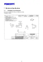
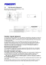
Page 20: ...31 7 Mechanical Specifications 7 1 Shielding Cover Dimension Dimension LxWxH 25 19mm x 18 56mm x 2 0mm Thickness 0 2mm...

Page 21: ...e de provoquer un fonctionnement ind sirable Radiation Exposure Statement This equipment complies with IC radiation exposure limits set forth for an uncontrolled environment This equipment should be i...

Page 22: ...EM sera charg de r valuer le produit final y compris l metteur et l obtention d une autorisation distincte au Canada End Product Labeling This transmitter module is authorized only for use in device w...

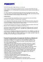
Page 23: ...priorit pour les bandes 5 250 5 350 MHz et 5 650 5 850 MHz et que ces radars pourraient causer du brouillage et ou des dommages aux dispositifs LAN EL Federal Communication Commission Interference St...

Page 24: ...this module installed IMPORTANT NOTE In the event that these conditions can not be met for example certain laptop configurations or co location with another transmitter then the FCC authorization is n...

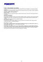
Page 25: ...spectrum modulation techniques Harmonized EN covering essential requirements under article 3 2 of the R TTE Directive EN 301 893 V1 7 1 2012 Broadband Radio Access Networks BRAN 5 GHz high performance...

Page 26: ...37...

Reviews: