background image


14 

5.  Enter  the  Reference  value:  this  is  the  temperature  value  you  expect  the  logger  to 

display.  

6.  Enter  the  MicroLite  value:  this  is  the  temperature  value  the  logger  is  currently 

displaying, when compared with the reference value. 

7.  Click 

Calibrate

 
To  restore  default  calibration,  click 

Default

.  This  will  remove  any  calibration  applied  to 

the MicroLite. 

2.3.6. 

Communication Setup 

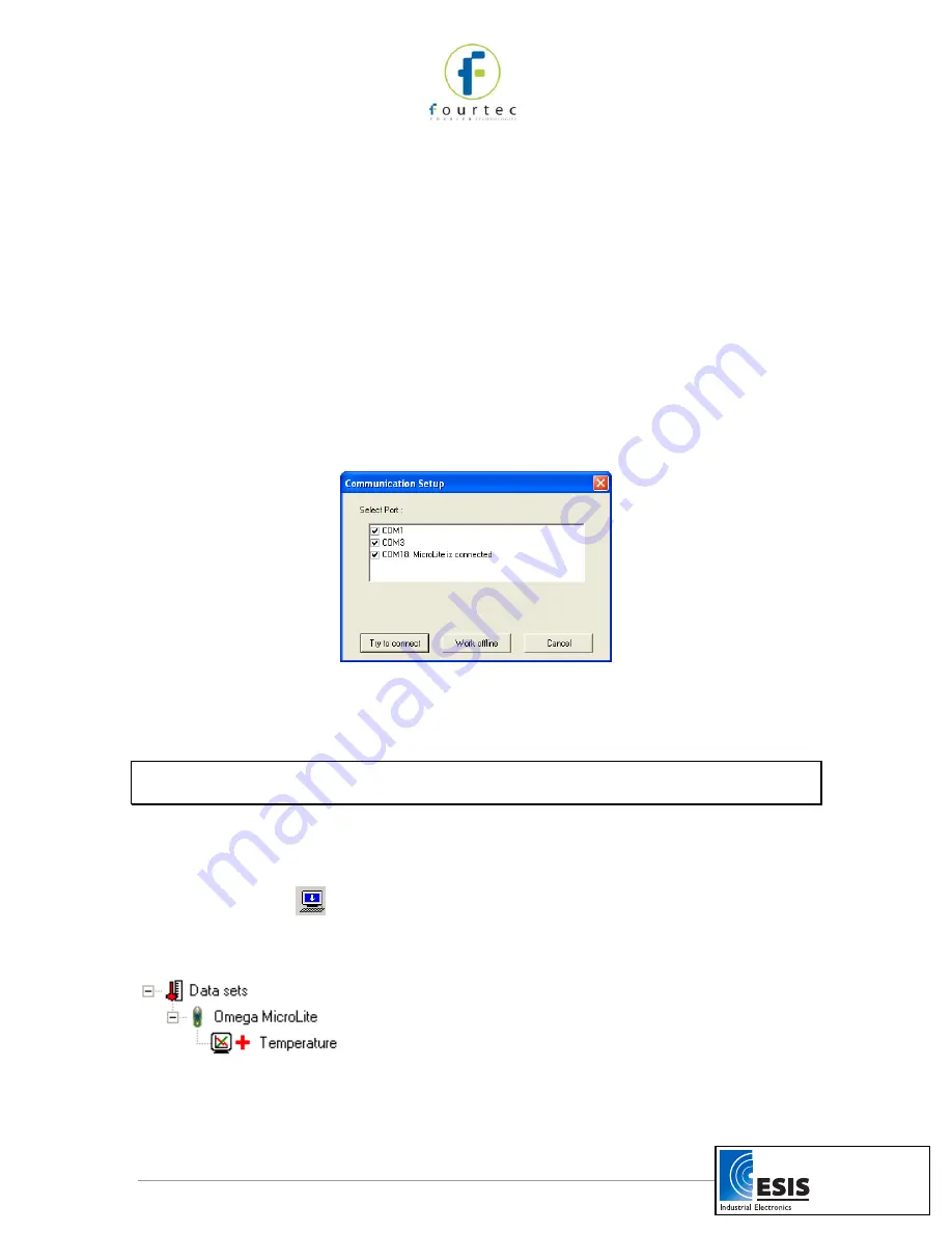
Communication  between  the  PC  and  the  MicroLite  unit  takes  place  automatically 
whenever  you  send  a  command  to  the  MicroLite.  However,  the  Communication  Setup


dialog box can be used for more advanced communication options. 
 
Click 

Logger

  on  the  main  menu  and  select 

Com  setup

  to  open  the 

Communication 

Setup

 dialog box: 


Figure 6: Communication Setup dialog box 

The selected COM ports are available for communication. 
1.  Click 

Try to connect

 to establish communication. 

2.  Click 

Work offline

 to work with saved files and no logger detection is required. 

Note:

  You  can  speed  up  the  MicroLite  detection  process  by  only  selecting  the  COM 

which is being used by the MicroLite. 

2.3.7. 

Downloading Data 

1.  Connect MicroLite to the PC. 
2.  Open the MicroLab Lite software. 

3.  Click 

Download


 on the main toolbar. 

The MicroLite will first be detected and then the download will begin. Once the data has 
been downloaded, it will be displayed both in the graph and in the table, and a new data 
icon will be added to the Data Map:  


You can now connect a different MicroLite to the PC and download its data as well. The 
number of downloads is limited only by the memory available on the computer. 

www.esis.com.au

Ph  02 9481 7420

Fax 02 9481 7267

[email protected]

Summary of Contents for MicroLab Lite

Page 1: ...MicroLite MicroLab Lite User Guide Fifth Edition April 2011 fourtec Fourier Technologies www esis com au Ph 02 9481 7420 Fax 02 9481 7267 esis enq esis com au...

Page 2: ...equirements 8 2 2 2 Installation Procedure 8 2 3 Getting Started 10 2 3 1 Setting up the MicroLite 10 2 3 2 Completing the Setup 12 2 3 3 Starting Data Recording 12 2 3 4 Stopping Data Recording 13 2...

Page 3: ...cture 20 2 5 12 Viewing more than one Data Set on the Graph 21 2 6 Analysis Tools 21 2 6 1 Setting the Analysis Tools Parameters 21 2 6 2 Histogram 22 2 6 3 Pasteurization 22 2 6 4 Statistics 23 2 7 T...

Page 4: ...ore Chapter 1 of this user guide details the operational procedures for MicroLite as a standalone device Chapter 2 provides instruction on how to work with the MicroLite software MicroLab Lite Contact...

Page 5: ...the placeholder on the MicroLite packaging Read more about the purpose of this magnet in section 1 6 3 on page 6 In order to save battery life MicroLite is shipped in Stop Mode This means that before...

Page 6: ...ou will be looking at the actual temperature recorded at that very moment MicroLite Alarm MicroLite displays an alarm notification whenever any alarm level is exceeded AL L The temperature reading is...

Page 7: ...s idle and is not recording When pressing Stop in the MicroLab Lite software the logger LCD immediately ceases to record data instead displaying STOP and scrolling through the alarm durations if alarm...

Page 8: ...he USB port the LCD will display STOP If the logger had recorded an alarm during the previous data logging session then the LCD will also scroll through the alarm durations 1 6 The MicroLite Battery T...

Page 9: ...te settings These can be restored the next time you Setup the logger using MicroLab Lite After replacing the battery the MicroLite LCD will display PUSH indicating it is in Push to Run mode Once you c...

Page 10: ...side the small holder next to the battery compartment for two seconds and then remove the magnet The MicroLite LCD will immediately move to Run mode and live temperature data will be displayed Magnet...

Page 11: ...To work with MicroLab Lite your system should be configured with the following Software Windows 2000 Windows XP Server 2003 and Vista Internet Explorer 5 0 or higher Hardware Pentium 200 MHz or higher...

Page 12: ...process The default installation location is C SiLabs 5 When the following dialog pops up click Install 6 The installation of the driver could take up to one minute or more depending on the system www...

Page 13: ...ally detect it Troubleshooting When connected to the PC USB port the MicroLite was not detected by the software Ensure that the USB driver was installed properly If it is then the MicroLite LED will l...

Page 14: ...option you want Celsius or Fahrenheit Temperature alarm Type in the desired Low and High alarm levels If the MicroLite records a reading that exceeds either of these levels the MicroLite s LCD will d...

Page 15: ...et to close the reed relay on the MicroLite s circuit board thereby causing the logger to start recording data This is convenient for when you wish to start recording data soon but not immediately fol...

Page 16: ...tion the calibration procedure is protected by a password The default password is 1234 To change the password 1 Click Logger on the main menu and then click Calibration 2 Click Change Password to open...

Page 17: ...munication Setup dialog box The selected COM ports are available for communication 1 Click Try to connect to establish communication 2 Click Work offline to work with saved files and no logger detecti...

Page 18: ...ave all the data sets select Save all from the File menu Note If you want to remove unwanted data before saving apply the Crop tool refer to page 19 2 4 MicroLab Lite Basics 2 4 1 Opening Files 1 Clic...

Page 19: ...o keep the graph clear and simple only two Y axes can be shown on the graph simultaneously If there are three curves in the graph one of the Y axes will be hidden To make this axis visible select the...

Page 20: ...t coordinates of the selected data recording will appear in the status bar at the bottom of the graph window To display a second cursor double click anywhere on the graph or click Second cursor on the...

Page 21: ...ick Graph Properties on the graph toolbar 2 Check the Use default zoom check box and click OK Every file and every data recording you download will automatically open in the default zoom as long as th...

Page 22: ...nes tab and then select the plot or axis you want to format in the Select plot drop down menu 3 From here you can format the line s color style and width as well as the markers color and style To remo...

Page 23: ...he file and then a new Excel workbook will be opened displaying the data along with the MicroLite info including the MicroLite name serial number and alarm levels setup If Excel is not installed on th...

Page 24: ...be displayed with the same recording date The MicroLab Lite data table below shows all data in the graph having the same time scale Figure 7 MicroLite data table Plot sync mode To display data on the...

Page 25: ...ta sets You can modify the histogram to your needs You can set the upper limits of the first bin and the lower limit of the last bins and refine the histogram by increasing the number of bins To modif...

Page 26: ...ow To hide the statistics click Statistics a second time 2 7 Toolbar Buttons 2 7 1 Main Upper Toolbar Open Opens saved files Save Saves the data that is currently displayed Print Opens the Print Optio...

Page 27: ...ation to the graph Move annotation Relocates the annotation on the graph Zoom in Activates the zoom tool Pan Activates the pan tool Autoscale Returns the graph to full view Graph properties Opens the...

Page 28: ...ductor enabling fast response time Software calibration is possible Outputs 3 digit 7 segment LCD with decimal point USB 2 0 interface Memory Capacity 8 000 samples or 16 000 samples depending on Micr...

Page 29: ...L Graphic analysis tools such as Markers Zoom Setup windows for setting the MicroLite unit name sampling rate and alarm level Sampling rate Once every second to once every two hours MicroLite sensor c...

Page 30: ...MICROLITE MAGNET HOLDER 7 FIGURE 4 LOGGER SETUP DIALOG BOX 11 FIGURE 5 CALIBRATION DIALOG BOX 13 FIGURE 6 COMMUNICATION SETUP DIALOG BOX 14 FIGURE 7 MICROLITE DATA TABLE 21 FIGURE 8 FUNCTIONS PARAMET...

Reviews: