Fountaine Pajot Helia 44 2019 Owner'S Manual Download Page 17

OWNER’S MANUAL / 

HÉLIA 44

OWNER’S MANUAL / 

HÉLIA 44

33

32

Systems

4

V  

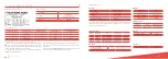
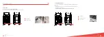
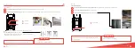
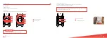
The steering system is a hydraulic system. Composed with a steering wheel which 
thanks to the starboard actuator leads a crossbar connecting the both stock arm of 
the rudder. 

V  

Periodic check to be performed: Check the slack of the different parts (rudder head, 
rudder, crossbar) and grease balls joints if necessary. 

For using the tiller, release the hydraulic circuit’s actuator thanks to the “by-pass” put 
in ON position. The emergency tiller is secured at the top of the port OR starboard 
rudder head. 

It is only designed for sailing at reduced speed in the event of damaged helm. 

Automatic pilot GARMIN (optional): 

The boat can be fitted with an automatic pilot 

GARMIN. The pilot fuse is located in the management box in the starboard engine 
compartment. The fuse of the control screen at the chart table is located under the 
saloon bench and the fuse of the control screen of the helm station is located in the aft 
cupboard of the starboard companionway.

STEERING SYSTEM

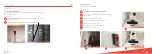
The emergency tiller is stored in a locker and must be easy accessible in 
all conditions.

WARNING

For more information, please refer to the drawing DDF_ACC_054_008

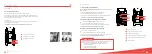
The on-board power is produced by the engine alternators (115Ah) and stored by 12V 
DC batteries.

The batteries are separated into 2 separate packs: 

Starboard engine/service battery pack = 4 x 150 Ah + 1 x 150 Ah (optional)

Port engine battery pack = 1 x 50 Ah

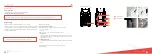
The port engine battery powers: 

The port engine only.

The starboard engine battery pack powers: 

The starboard engine.

All the 12V functions on the electrical panel. 

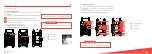
The 3 fuses panels are positioned as follows: 

1 under the saloon bench

1 in the aft cupboard of the port companionway

1 in the aft cupboard of the starboard companionway

The content of each box is detailed on the lid.

ELECTRICITY

For more information, please refer to the drawing DDF_ELC_054_733

12V DC engines network

Battery coupling : 

V  

The coupling between the service battery pack and the engine battery is 
triggered when the voltage on one of the packs exceeds 13,2V.

V  

The coupling is maintained until the pack voltage falls below 12,8V.

V  

When the voltage is below 12,8V, the coupling is interrupted and the engine 
battery is then isolated from the starboard service battery pack

V  

The BACKUP/START-UP circuit breaker (for right) permits the coupling of the 
battery packs. If one of the engines doesn’t start, switch on the circuit breaker. 
When the engine is running, switch off directly the circuit breaker.

WARNING

Backup/start-up circuit breaker 

Summary of Contents for Helia 44 2019

Page 1: ...H LIA 44 OWNER S MANUAL...

Page 2: ...18 V Mooring and towing 19 3 Equipments page 21 V Deck 22 24 V Hull saloon 25 29 4Systems page 31 V Steering system 32 V Electricity 33 35 V Gas circuit 36 V Water 37 45 Manoverboard prevention 5 and...

Page 3: ...1 Technical Specifications V Manufacturer s plate 6 V Identity sheet 6 V Design category 6 V Characteristics 7 H LIA 44...

Page 4: ...hy it is important to respect the sail reduction table General LENGTH LH 13 30 m 43 50 ft HULL WIDTH BH 7 40 m 24 3 ft DRAUGHT 1 16 m 3 8 ft AIR DRAUGHT 21 65 m 71 ft LIGHT DISPLACEMENT 12 837 kg MAXI...

Page 5: ...Sailing V Entrance door 10 V Leaving the harbour 10 12 V Starting the engines 13 14 V Sailing 15 16 V Arriving in a harbour 17 V Anchorage 17 18 V Mooring and towing 19 2 H LIA 44...

Page 6: ...ck all the doors and lockers Then check that the bilges are empty of water Check that the hatch of the life raft is unlocked and hang outside the se curity fittings buoy A second life raft can be inst...

Page 7: ...ilings V Front beam e V Fly f V Mast g In strong winds fix all mobile elements 6 13 12 11 10 7 8 9 LEAVING THE HARBOUR NEXT 1 3 2 Check the engine and base levels every month See paragraph maintenance...

Page 8: ...ach on the front points but on the bowsprit WARNING SAILING Using the asymmetrical spinnaker or the genaker optional The asymmetrical spinnaker and the genaker are sails that are designed to be used i...

Page 9: ...e tack point is at 10cm approximatively above the boom 1 2 3 4 Classic reef system reef 2 et 3 Release the mainsail sheet Release the mainsail s halyard Strap the tack point Haul up the mainsail s hal...

Page 10: ...damage davit or hulls Clamp the hoist to avoid the anchor moving on the davit 1 2 3 4 5 6 7 Raising the anchor During the operation stay away from the windlass and the chain and make sure that you pro...

Page 11: ...V Deck 22 24 V Hull saloon 25 29 3 Equipments H LIA 44...

Page 12: ...V Fresh water valve b a All versions a b Solar panels optional The boat can be fitted with 4 solar panels a fixed behind the mainsail rail on the bimini The 12V connection is done on the service batt...

Page 13: ...d maintenance see the manufacturer s manual HULL SALOON If the service battery charge level is 11 7V the refrigerator switches to safety Follow these instructions to minimize the 12V energy consumptio...

Page 14: ...the manufacturer s manual 1 2 b V Sea water valves c V Power generator d V Control remote 3 Equipments The power generator must not run empty as it may destroy the pump WARNING a V Air conditioning st...

Page 15: ...pments HULL SALOON NEXT Watermaker optional The boat can be fitted with a watermaker located in the fore starboard technical compartment Depending on the chosen watermaker type 12V or 220V a specific...

Page 16: ...V Steering system 32 V Electricity 33 35 V Gas circuit 36 V Water 37 45 Systems 4 H LIA 44...

Page 17: ..._054_008 The on board power is produced by the engine alternators 115Ah and stored by 12V DC batteries The batteries are separated into 2 separate packs V Starboard engine service battery pack 4 x 150...

Page 18: ...0V depending on the chosen option Switch on the differential circuit breaker and the circuit breaker s for the function required Never connect an extension with a damp plug WARNING 220V 110V AC networ...

Page 19: ...f valves of appliances a to used They are located in the kitchen cupboard right under the sink valves open in the direction of the pipe 1 2 For more information please refer to the drawing DDF_PLB_054...

Page 20: ...WATER NEXT Seawater intake valve Systems 4 Using the toilets The toilets are fitted with a holding tank MANUAL WC The evacuation valve must be closed while in the harbour Check that the sea water inta...

Page 21: ...V Seawater intake valves b V Evacuation valves WATER NEXT Systems 4 ELECTRICAL WC OPTIONAL The boat can be fitted with electrical WC These WC are protected by a 25 A circuit breaker The starting up is...

Page 22: ...ed By pumping the waste deck fillers 1 2 For more information please refer to the drawing DDF_PLB_054_805 WATER NEXT Systems 4 Each hull is fitted with a lift pump These pumps are protected by a 10A c...

Page 23: ...umps with an automatic trigger V 1 per engine compartment V 1 per hull Activate the switch on the electrical panel 2 possible positions 1 AUTO position The bilge pumps are triggered automatically if a...

Page 24: ...Manoverboard prevention and man recovery 5 H LIA 44...

Page 25: ...roof mast step etc are covered with an antiskid surface or teak covering which allows the crew to move on the boat in a secure way It is also recommended according to sea or wind conditions to wear sa...

Page 26: ...Fire protection 6 H LIA 44...

Page 27: ...s hose and trigger the extinguisher according to the manufacturer s instructions If you choose to install a carbon dioxide extinguisher it can only be installed in areas with powered up electrical equ...

Page 28: ...Preparing the winter season Handling V Water circuit 56 V Outside 56 V Engines 56 V Preparation 56 V Craning 56 7 H LIA 44...

Page 29: ...e hull and deck thoroughly V Prevent rubbing of ropes and moorings V To protect the engines please refer to the manufacturer s recommendation V The wintering of the engines must be carried out by a pr...

Page 30: ...Maintenance V Drainage 60 V Running rigging sheets and ropes 61 V Periodic maintenance chart 62 64 8 H LIA 44...

Page 31: ...core 12 16fx 12 23 Reef 2 Polyester 24fx Polyester braided core 12 16fx 12 30 Reef 3 Polyester 24fx Polyester braided core 12 16fx 12 33 Lazy 1 Polyester 16fx polyester core 6 25 Lazy 2 Polyester 16fx...

Page 32: ...e rigging ANNUALY Check the blocking of the mainsail s shackle ANNUALY Check and tightening gardrails QUARTERLY WARNING Anchorage windlass Steering system Electricity Power generator optional Engines...

Page 33: ...ilters MONTHLY General check by manufacturer SEE MANUFACTURER S INSTRUCTIONS Clean suction strainers ANNUALY MAINTENANCE Test electrical and manual bilge pumps IN THE BEGINNING IN USE Check water grou...

Page 34: ...Fountaine Pajot S A Z I 17 290 Aigrefeuille France fountaine pajot fountaine pajot com www fountaine pajot com cr ation graphique Seelab Studio www seelab fr...

Reviews: