6
5
8
7
1
2
3
4
285mm
.00
142.5mm
.00
95.00mm
190.00mm
285.00mm
380.00mm
Quick Installation Guide
Security Warning
1
3
NVR Structure
Model: FN3104W-B4
V1.0.2
EQ310417
2
Package Contents
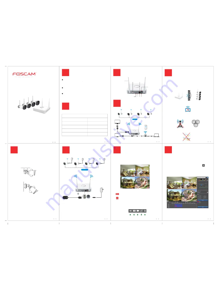
VGA Output
Power Input
(DC12V / 2A)
HD-OUT
Reset USB
Power Switch
Ethernet Port
6
Cameras Installation
Please Note:
Ensure that the rain or water will not reach the connector
ports at the end of the pig tail wiring. These connectors are
not weather-resistant.
Fixate the camera on your preferred location and use screws to
mount it. We have provided screws in the package.
0~90°
0~360°
0~360°
0~90°
0~360°
0~360°
4 Power Adapters for IPC 1 Power Adapter for NVR
Quick Installation Guide Warranty Card
Please change the password of your Foscam NVR APP account,
NVR and cameras username regularly, the password should be
the combination of numbers, letters and special characters.
Please keep the username and password of your cameras, NVR
and Foscam NVR APP account safe.
Please update your camera to the latest
fi
rmware, which make
you have better product experience and ensure the safety of
your NVR and cameras.
4-Channel NVR
1.5m (5 ft) Ethernet Cable
720P Bullet IP Cameras
4
Wireless Connection
Monitor
VGA Cable
VGA
VGA
Router
Computer
HD-OUT Cable
TV
HD-OUT
LAN
Ethernet Cable
LAN
Foscam NVR
LAN
HD-OUT
WiFi Connection
8
Preview
5
Interference
7
Power On
DC 12V/2A
Mouse
WiFi Connection
GND
Connect the powers as the
fi
gure above, and make sure the
NVR is connected to the ground, then turn on the power
switch on the rear panel.
After the NVR starts up successfully, the Power LED, HDD LED
and LAN LED indicators will turn green.
DC 12V/1A
DC 12V/1A
DC 12V/1A
DC 12V/1A
For the initial login, please set a new password and follow the
Setup Wizard to
fi
nish the setting.
Note:
It may take 1 to 2 minutes for the Live View interface appear, please wait
patiently.
Left click with the mouse once on one of the live video
channels available, the toolbar will pop up.
Status Icons
This icon indicates that this camera is currently recording.
This icon indicates that the motion detection of this
camera has been triggered.
Toolbar
1: Audio 2: Playback 3: Recording 4: Camera Name 5: Full Screen
1
2
3
4
5
9
Playback
2016-08-11 10:15:36
FI9800W
2016-08-11 10:15:36
FI9800W
2016-08-11 10:15:36
FI9800W
2016-08-11 10:15:36
FI9800W
2016-08-11 10:15:36
FI9800W
2016-08-24 10:15:36
FI9800W
2016-08-11 10:15:36
FI9800W
2016-08-11 10:15:36
FI9800W
2016-08-11 10:15:36
Antenna
2016-08-11 10:15:36
2016
You can view the recording video of the cameras.
Steps:
Right click the mouse in the Live View mode, select the
Playback > Date > Video Type > Search
, then click to view
recording video.
Note:
The green date indicates there is recording
fi
les on the day.
2016-08-24 10:15:36
FI9800W
2016-08-11 10:15:36
FI9800W
2016-08-24 10:15:36
FI9800W
2016-08-11 10:15:36
FI9800W
USB Mouse
Screw Pack
CD
/
A clear line-of-sight connection between NVR and IP cameras provides
the strongest wireless signal up to 525ft / 160m away. The signal may be
weakened in the scenarios below.
1. There is a barrier between NVR and IP cameras, such as wall made of
cement, iron, tree, etc.
2. There is other electrical equipment running nearby, such as
microwave oven, fridge,
etc.
3. WiFi NVR is placed near other wireless signal sources, such as radio
transmitting tower, voltage transformer, other wireless router, etc.
4. The weather is bad, such as rainy, thundering, cloundy, etc.
Antenna C
Antenna A
Antenna B


