

© Copyright 2007 Fortinet Incorporated. All rights reserved.
Products mentioned in this document are trademarks or registered trade-
marks of their respective holders.
Regulatory Compliance
FCC Class A Part 15 CSA/CUS
27 April 2007
Checking the Package Contents
Connecting
Planning the Configuration
Esc
Enter
CONSOLE
10/100
10/100/1000
USB
1
2
3
4 5 6
Rack-Mount Brackets
Ethernet Cables:
Orange - Crossover
Grey - Straight-through
Power
Connection
Power
Switch
RJ-45 to
DB-9 Console Cable
Power Cable
Back
Esc
Enter
CONSOLE
10/100
10/100/1000
USB
1
2
3
4 5 6
Front
LCD
Control
Buttons
Power
LED
USB
Serial
Console
Port 5,6
(Future use)
-
Port1
Port 2,3,4
HA
Documentation
FortiManager 400A
Copyright 2006 Fortinet Incorporated. All rights reserved.
Trademarks
Products mentioned in this document are trademarks.
Q u i c k S t a r t G u i d e
Esc
Enter
CONSOLE
10/100
10/100/1000
USB
1
2
3
4 5 6
Straight-through Ethernet cable connects
to hub or switch on the network
Ethernet for high
availability connections
Power cable connects to power outlet
Esc
Enter
CONSOLE
10/100
10/100/1000
USB
1
2
3
4 5 6
(Future use)
-
Connector
Type
Speed
Protocol
Description
Port 1
RJ-45
10/100 Base-T
Ethernet
Connection to the network
Ports 2,3,4
RJ-45
10/100 Base-T
Ethernet
For future use.
Ports 5 and 6
RJ-45
10/100/1000 Base-T Ethernet
For future use.
CONSOLE
RJ-45
9600 bps
RS-232 serial
Optional connection to the management computer.
Provides access to the command line interface (CLI).
Place the unit on a stable surface. It requires 1.5 inches (3.75 cm) clearance above and
on each side to allow for cooling.
Alternatively, Mount the unit in a standard 19-inch rack. The FortiManager 400 system
requires 1 U of vertical space in the rack.
Connect the network cable to interface 1.
•
•
•
Connect the FortiManager System to a power outlet and to the internal and external networks.
FortiManager 400A
02-30003-0243-20070427
FortiManager Server LED Indicators
LED
State
Description
Power
Green
The FortiManager Server unit is powered on.
Off
The FortiManager Server unit is powered off.
All Ports
Amber (Left LED)
The correct cable is in use and the connected equipment
has power.
Flashing Amber
(Left LED)
Network activity at this interface.
Off (Right LED)
The interface is connected at 10 Mbps.
Green (Right LED)
The interface is connected at 100 Mbps.
Red (Right LED)
Ports 5 and 6 are connected at 1000 Mbps.
To power up the FortiManager Server, connect the power cables to the power outlets.
After a few seconds, SYSTEM STARTING appears on the LCD. The menu selections appear
when the unit is up and running.
If you connect only one power source, an audible alarm sounds to indicate a failed power
supply. To stop this alarm, press the red alarm cancel button on the rear panel next to the
power supply inputs.
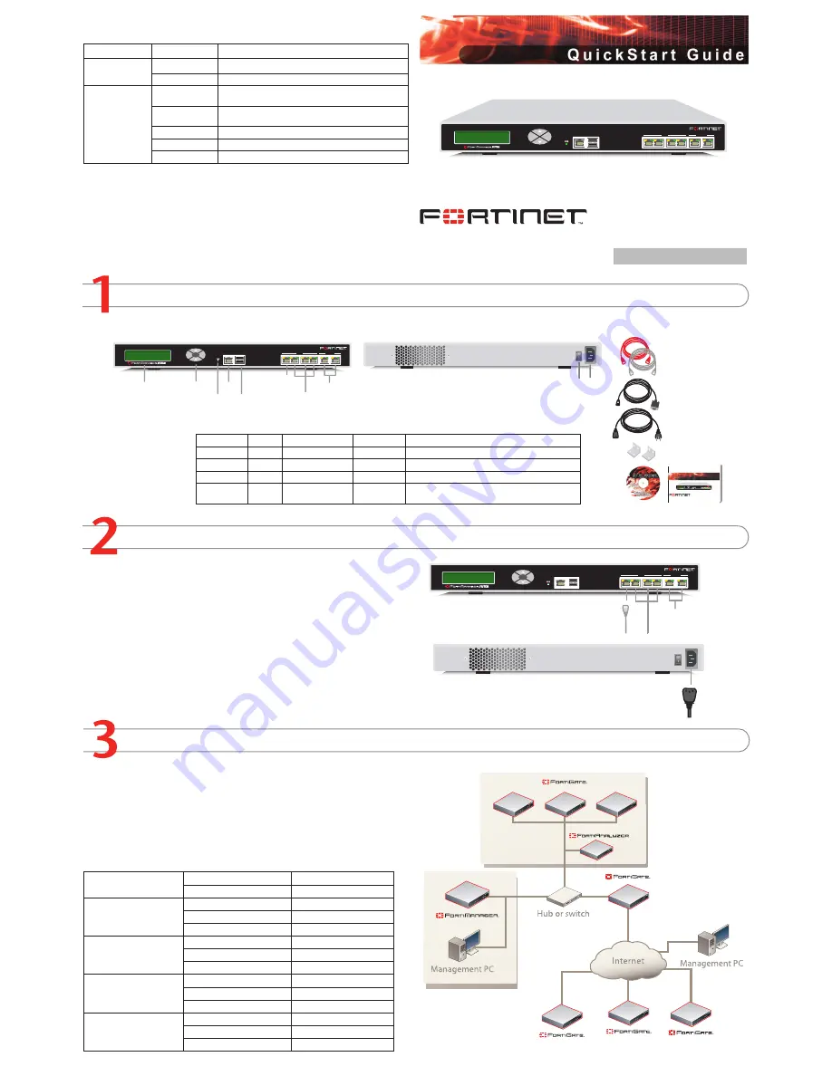
The FortiManager System is an integrated management and monitoring tool that consists of
one or more FortiManager Servers and managed FortiGate and FortiAnalyzer devices.
The FortiManager Server manages communication between FortiGate devices, and a
FortiAnalyzer device. The FortiManager Server stores and manages all FortiGate device
configurations. It can also act as an on-site FDN server for the FortiGate devices to down
-
load virus and attack signatures, and to use the web filtering and antispam service. The
FortiManager Server can also connect to a FortiAnalyzer unit for managing and monitoring
logs and reports for all managed FortiGate devices.
Factory Defaults
Administrator Account
User name:
admin
Password:
(none)
Port 1
IP:
192.168.1.99
Netmask:
255.255.255.0
Management Access:
ping, https, http, ssh
Port 2
IP:
0.0.0.0
Netmask:
0.0.0.0
Management Access:
Port 3
IP:
0.0.0.0
Netmask:
0.0.0.0
Management Access:
Port 4
IP:
0.0.0.0
Netmask:
0.0.0.0
Management Access:


