

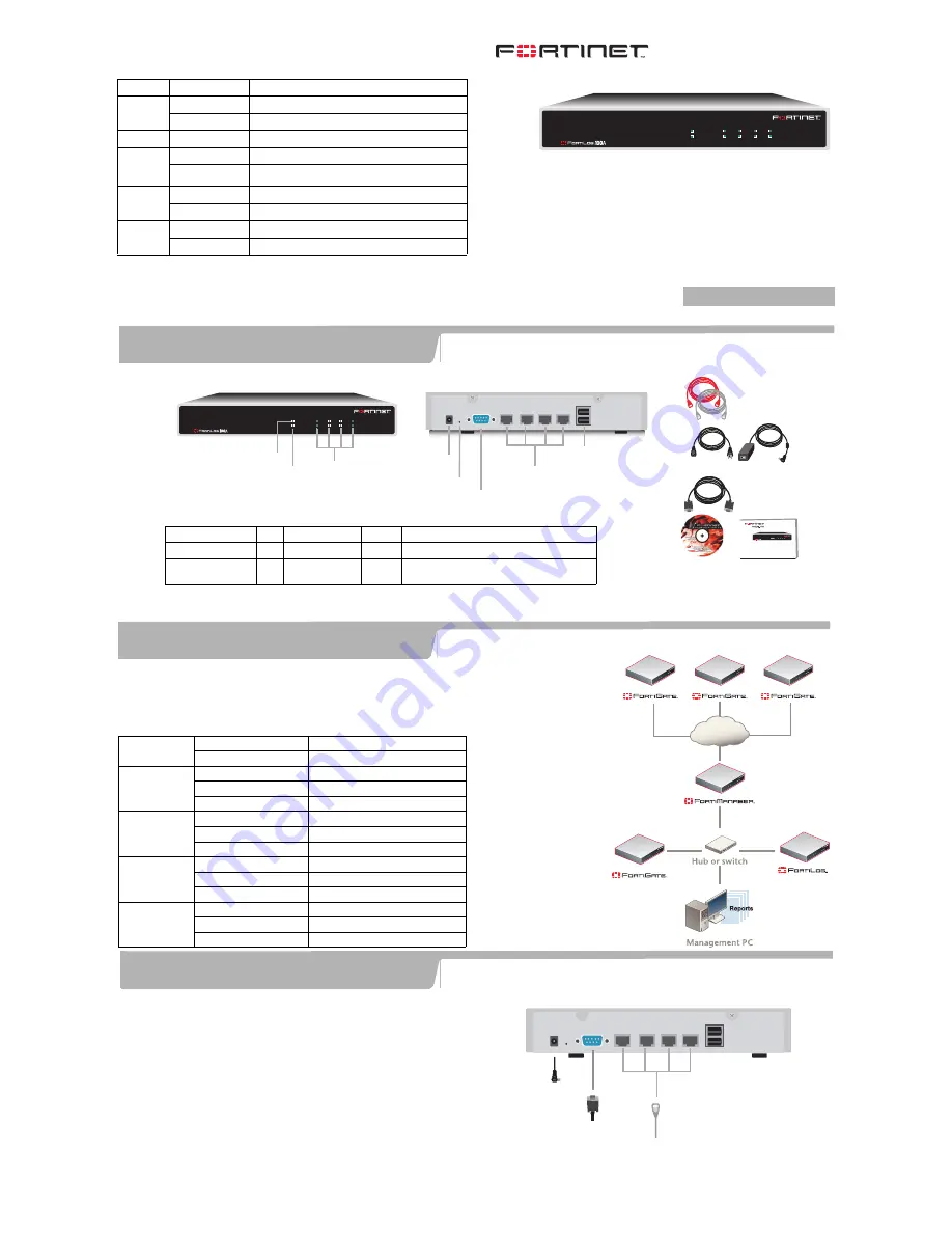
Straight-through Ethernet cable connects
to hub or switch on the network
Power cable connects
to power supply
1
2
3
4
DC+12V
USB
Optional null modem cable connects to
serial port on management computer
Back
Internal Interface,
switch connectors
1,2,3,4
Reset
Power
Connection
USB
(future)
1
2
3
4
DC+12V
USB
RS232 Serial
Connection
Ethernet Cables:
Orange - Crossover
Grey - Straight-through
Documentation
QuickStart Guide
Copyright 2005 Fortinet Incorporated. All rights reserved.
Trademarks
Products mentioned in this document are trademarks.
Null-Modem Cable
(RS-232)
POWER
STATUS
4
3
2
1
LINK / ACT
10/100
Front
POWER
STATUS
4
3
2
1
LINK / ACT
10/100
Power LED
Status LED
Interface
status LEDs
Power Cable Power Supply
POWER
STATUS
4
3
2
1
LINK / ACT
10/100
Internet
Connector
Type
Speed
Protocol Description
Ports 1, 2, 3, 4
RJ-45 10/100Base-T
Ethernet
Connection to the network.
CONSOLE
DB-9
9600 bps
RS-232
serial
Connection to the management computer.
Provides access to the command line interface (CLI).
FortiLog unit LED Indicators
LED
State
Description
Power
On
The FortiLog unit is powered on.
Off
The FortiLog unit is powered off.
Status
On
The FortiLog unit is running normally.
Ethernet
ports
(back)
Flashing
Network activities at this interface.
Off
No link at the interface.
10/100
On
The interface is connected at 100 Mbps.
Off
The interface is connected at 10 Mbps.
Link Act
Flashing
Network activities on the FortiLog unit
On
Interface connected.
Check that the package contents are complete.
QuickStart Guide
Checking the package contents
1
Things you need to know before installing the FortiLog unit.
You can add the FortiLog unit to your local FortiGate network to receive log messages from your local FortiGate units, or
connect the FortiLog unit to the FortiGate units remotely using FortiManager. To connect the FortiLog unit to the
FortiGate units remotely, you must configure the DNS server and the default gateway.
To manage the FortiLog unit, you can use a computer within the local network or over the Internet.
Factory Defaults
Administrator
account
User name:
admin
Password:
(none)
Port 1
IP:
192.168.1.99
Netmask:
255.255.255.0
Management Access:
ping, https, ssh, http
Port 2
IP:
192.168.2.99
Netmask:
255.255.255.0
Management Access:
ping, https, ssh, http
Port 3
IP:
192.168.3.99
Netmask:
255.255.255.0
Management Access:
ping, https, ssh, http
Port 4
IP:
192.168.4.99
Netmask:
255.255.255.0
Management Access:
ping, https, ssh, http
Planning the installation
2
Connecting the FortiLog unit
3
Connect the FortiLog unit to a power outlet and to the network hub or switch.
•
Place the FortiLog unit on a stable surface. It requires 1.5 inches (3.75 cm)
clearance on each side to allow for cooling.
•
Make sure the power is not plugged into the wall before connecting the power
cable.
•
The Status light flashes while the unit is starting up and remains lit when the
system is up and running.
© Copyright 2005 Fortinet Incorporated. All rights reserved.
Trademarks
Products mentioned in this document are trademarks or registered trademarks of their respective holders.
Regulatory Compliance
FCC Class A Part 15, CE, and UL
12 August 2005
For technical support please visit http://www.fortinet.com.
FortiLog-100A
01-30000-0223-20050812


