


Connecting a FortiGate-5140B PEM to DC power
Power connection and configuration
FortiGate-5140B Chassis Guide
24
01-500-156415-20151104
You need the following equipment to connect a FortiGate-5140B PEM to DC power:
•
An electrostatic discharge (ESD) preventive wrist strap with connection cord.
•
Two black AWG-6 stranded wires labelled -48V with attached 3/4-inch listed closed
loop double-hole lugs with insulating boot suitable for the DC cables used, such as
Thomas & Betts PN 256-30695-1225.
•
Two red AWG-6 stranded wires labelled RTN with attached 3/4-inch listed closed loop
double-hole lugs with insulating boot suitable for he DC cables used, such as Thomas
& Betts PN 256-30695-1225.
To connect a FortiGate-5140B PEM to DC power
1
Attach the ESD wrist strap to your wrist and to an ESD socket or to a bare metal
surface on the chassis or frame.
2
Make sure that the PEM and power cord are not energized.
3
Remove the first set of nuts and lock washers from both connectors on the PEM.
4
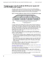
Connect two black -48V power wires from the DC power source to the connectors on
the FortiGate-5140B PEM labeled - (the connectors on the right side of the PEM)
using the double-hole lugs (see
).
Install each double-hole lug vertically. Do not apply torque of more than 3.8 Nm (33.62
lbf.in).
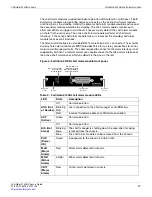
Table 6: FortiGate-5140B PEM LEDs
LED
State
Description
REV. VOLTAGE
(Reverse
Voltage)
Off
Normal operation
Solid Red Input voltage polarity reversed.
FUSE CH1-4
(Fuses for power
channels 1 to 4)
Off
Normal operation.
Solid Red Fuse blown or absent.
Blinking
Red
Input power lost
FUSE FANS
(Fuses for the
cooling fan
power channel)
Off
Normal operation.
Solid Red Fuse blown or absent.
Blinking
Red
Input power lost.
If all five fuse LEDs are simultaneously blinking input power to the PEM has been lost.
ACTIVE
Solid
Green
Normal operation.
OOS (Out of
Service)
Off
Normal Operation.
Blinking
Red
Lost connection to shelf manager or IPMB bus.
Solid Red Incorrect hardware address or FRU data corruption.
H/S (Hot Swap)
Off
Normal operation.
Blinking
Blue
The PEM is shutting down in preparation for being
removed from the chassis.
Blue
The PEM can be removed from the chassis.