background image

47

2. Setting Up a Job

Getting Started

Turning the Machine On/Off

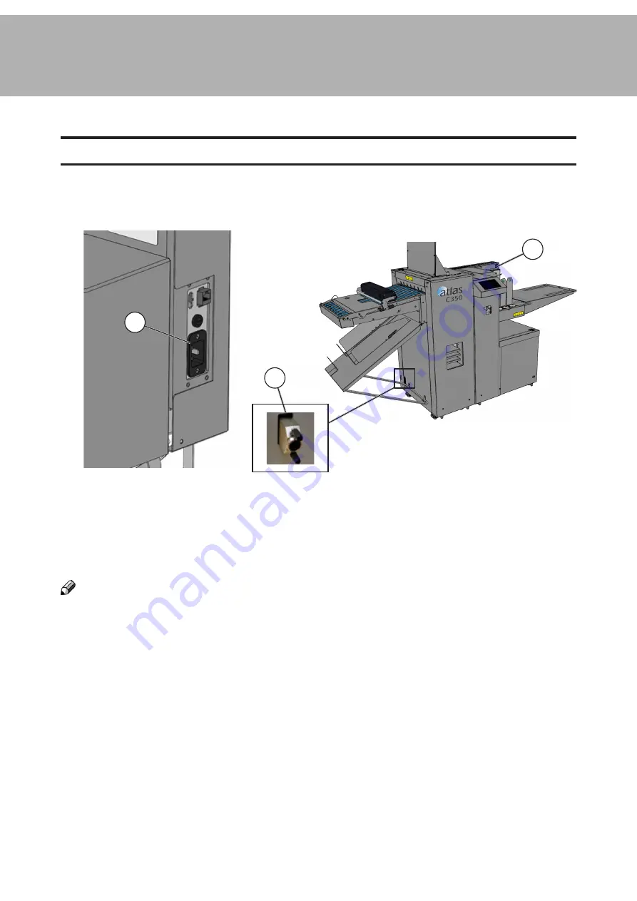
1. Ensure the main power cord is plugged into the machine [A] and the wall socket.

2. Ensure the CAN termination plug [B] is plugged in.

3. Toggle the main power switch [C] to turn the machine on.

4.

To turn the machine off again toggle the main power switch [C] again.

NOTE:

If the CAN termination plug is not plugged in the machine may not function correctly.

B

C

A

Summary of Contents for Atlas C350

Page 1: ...Atlas C350 Automatic Air Feed Programmable Folder Creaser OPERATOR MANUAL 10 2021...

Page 2: ...which case the user may be required to take adequate measures The product System which is connected to this machine will be class A NOTE The domestic environment is an environment where the use of bro...

Page 3: ...RNING Indicates a potentially hazardous situation which if instructions are not followed could result in death or serious injury CAUTION Indicates a potentiality hazardous situation which if instructi...

Page 4: ...oper grounding of the equipment can result in electrical shock Never connect the machine to a power source that lacks a ground connection terminal This machine is destined for specific purpose only An...

Page 5: ...under the machine Always contact service if relocating the equipment Do not move the machine while the machine is running Do not open covers while the machine is running Do not switch off the power w...

Page 6: ...Page intentionally blank...

Page 7: ...nal 29 Setting Crease Tilt Knob 30 Perforation 32 About Perforation 32 Rotary Perforation 33 Rotary Perforation 33 Cross Perforation 38 Blade removal replacement 38 Anvil strip removal replacement 41...

Page 8: ...ed Jam in the Feeder 73 Misfeed Jam in the Folder 73 Fault Codes 74 List of Fault Codes 74 Accuracy Checks 80 Alignment Calibration Check 80 Separation Pad Check 82 Creaser Calibration Check 83 Fold C...

Page 9: ...a single pass The Atlas C350 is built with the easy open design suction feeder that handles sizes from 210 1300mm 8 3 51 2 in length As the Atlas C350 creases and folds in one non stop pass the precis...

Page 10: ...uum belts underneath 6 Paper guide tongues 7 Infeed alignment wall 8 Infeed table 9 Crease only delivery 10 Storage shelves 11 User interface UI 12 Feeder skew adjustment wheel 13 Magnetic paper guide...

Page 11: ...ight for sheets shorter than 700 mm 27 6 9 Maximum paper stack height for sheets longer than 700 mm 27 6 10 Paper stack height sensor Q4 11 Separated paper SP sensor Q12 12 Feeder skew adjustment whee...

Page 12: ...7 1 Crease skew adjustment 2 Rotary tool carrier 3 Dynamic Crease unit 4 Dynamic Crease pressure lock 5 Dynamic Crease pressure adjustment 6 Paper path can be replaced with an optional static creaser...

Page 13: ...buttons will stretch to fit the screen This manual will most often show a fully configured system The control panel is a touchscreen Point at the screen and press the button to reach the desired funct...

Page 14: ...e included with the Atlas C350 Part number Description 601 167 Digital thickness gauge 1 99 12 28T rotary perforation blade 7 TPI 1 99 35 Rotary perforation slitting anvil 142 115551 Multi purpose wre...

Page 15: ...blades as well as scorers are available for purchase Part number Description Upgrade kits AC 150 10 Additional Static Creaser Assembly Dynamic Crease Blade kits AC 150 60 Dynamic Crease Blade first st...

Page 16: ...16 Page intentionally blank...

Page 17: ...ese differences Be prepared to make small adjustments to the machine to stop any problems that they might cause Guidelines Always make sure that the sheets of paper you use are cut square This machine...

Page 18: ...weak along the edges of the crease This allows the paper to fold accurately along the crease The Quick Release Blade Set optional can crease and or perforate optional sheets accurately at a rate of 8...

Page 19: ...a good crease on thick paper and thin card To do this it makes a wide crease A wide crease is necessary because it gives sufficient material at the spine of the fold The Narrow blade set is designed t...

Page 20: ...roduce up or down facing creases without flipping the stack of paper NOTE Optional blade sets to produce narrower crease are available To flip the crease blade set or replace it with another set 1 Fro...

Page 21: ...Loosen the locking knobs in red in the direction indicated by the arrows A 5 Slide the Locking knobs in red to the centre B to release locking pins 6 Pull the blade set upwards to remove it C Continu...

Page 22: ...Blade Links and Bridge to new blade set and reinsert Continued on next page NOTE A label on the blade set indicates paper movement direction Ensure the blade set is in stalled in the correct direction...

Page 23: ...r 10 From the touchscreen interface choose Tools Change Crease Blades 11 Use this menu to choose the blade set that has just been installed and set its direction crease up or crease down Click the gre...

Page 24: ...w or too deep loosen the locking knobs 3 Adjust pressure lever on the DynaCrease bridge as shown A shallower crease B deeper crease A B 4 Tighten the locking knobs Counter 2300 Batch 23 50 Jobs Home T...

Page 25: ...is too much material at the spine of the fold the fold might not be accurate or square An Extra Narrow blade set is also available for purchase The Extra Narrow blade set is designed to make a very n...

Page 26: ...or to cross perforate are available see the Choose the Correct Quick Release Blade Set section within this manual To flip the crease blade set or replace it with another set 1 Open the top cover 2 Pus...

Page 27: ...rect direction Installing the blade backwards may result in poor crease quality and paper jams 4 Lift the Bridge Assembly up and remove it 5 Pull the blade set upwards to remove it 6 Insert the new bl...

Page 28: ...he touchscreen interface choose Tools Change Crease Blades 10 Use this menu to choose the blade set that has just been installed and set its direction crease up or crease down Click the green check ma...

Page 29: ...If the crease is too shallow or too deep use the adjustment lever on the Quick Release Blade bridge as shown A shallower crease B deeper crease A B Counter 2300 Batch 23 50 Jobs Home Tools Media Coun...

Page 30: ...s are marked in red correct crease position is marked in green NOTE In the below image the optional additional static creaser is shown 2 If the crease is skewed adjustment is necessary Crease Feed dir...

Page 31: ...er to the left or to the right depending on the direction of the crease skew 5 Rotate the knob clockwise to secure it 6 Run another proof sheet to check if the crease is now perpendicular to sheet edg...

Page 32: ...e process direction using rotary tools Across the process direction using the optional cross perforation kit Feed direction Rotary perforation Cross perforation Depending on paper type and the desired...

Page 33: ...ive tires relative to the drive hubs it is possible to steer the sheet i e by placing the tire on top of the hub on one side of the paper only To set up rotary perforation a perforation blade and an o...

Page 34: ...hubs in order to mount the blade 4 Mount a matching pair of blades C and secure them to the drive wheel using a 2 5 mm hex key 5 Using a 2 mm hex key loosen one of the drive hubs E and slide it away f...

Page 35: ...er to set the 0 1 mm 0 004 gap between the blade and the anvil Do not force the blade against the anvil to prevent damage 9 Place the rotary tool carrier back in the machine and close the top cover 10...

Page 36: ...ts on the paper table in the corner and adjust magnetic paper guides if necessary 17 Run a proof sheet and inspect the output If further adjustment is necessary repeat steps 13 to 16 NOTE When not in...

Page 37: ...37 1 Page intentionally blank...

Page 38: ...ext page Blade removal replacement 1 Locate the Allen tools supplied with the Cross Perforation kit 2 Place the cross perforation tool on a table in the orientation shown below 3 Remove one guide bolt...

Page 39: ...xtreme caution Leather gloves must be worn whenever handling the blades E Double stacking is NOT supported OK OK OK NO Continued on next page 5 Loosen grub screws A x13 Shown on previous page 6 Lift o...

Page 40: ...exceed the notch B Shown on previ ous page 10 Tighten grub screws A x13 11 Rotate the bottom assembly 180 back into line with the top assembly 12 Replace bolt C and spring D and tighten WARNING All b...

Page 41: ...ution Leather gloves must be worn whenever handling the blades Anvil strip removal replacement D C A B Continued on next page NOTE Each anvil strip can be used twice When perforation is no longer effe...

Page 42: ...ews A x5 Shown on previous page 6 Lift out the anvil strip E 7 Rotate anvil strip 180 Or Replace with spare 8 Insert the anvil strip into the anvil channel 9 Ensure the anvil strip is fully inserted a...

Page 43: ...be worn whenever handling the blades Perforation depth adjustment procedure A B C A NOTE Before adjusting depth of perforation ensure the anvil strip does not require replacement 4 Turn nut s C anti c...

Page 44: ...d knives and can make up to two parallel folds on each sheet A cross sectional view of the fold mechanism is shown below A B C F E This machine has many different fold configurations available The fol...

Page 45: ...used to fold the document becomes a deflector This means that the machine aligns the fold knife with the lead edge or spine of the document to guide it through the machine A Half Fold K1 cycle means K...

Page 46: ...46 1 Page intentionally blank...

Page 47: ...to the machine A and the wall socket 2 Ensure the CAN termination plug B is plugged in 3 Toggle the main power switch C to turn the machine on 4 To turn the machine off again toggle the main power swi...

Page 48: ...surface as shown Continued on next page 2 Bend the paper stack 3 Use your fingers and thumbs to pinch the paper stack 4 With the paper pinched between your fingers straighten out the paper stack Befo...

Page 49: ...to break surface tension and preseparate the sheets 6 Realign the sheets into a stack before putting them into the tray NOTE If the sheets you are using are too stiff or too large format to carry out...

Page 50: ...within the marked area of the picture from the center to the leading edge in paper feed direction 2 Measure the lowest point of the stack of paper 3 Measure the height of the leading edge of stack of...

Page 51: ...he optional Feeder Table Extension section within this manual NOTE To make sure the magnetic paper guides are not too tight put a single sheet of paper between the stack and the guide when setting the...

Page 52: ...using sheets longer than 700 mm 27 6 1 Ensure the built in pull out table A is fully stowed 2 Hook the table extension B into the lift C as shown NOTE The feeder table extension has a built in pull o...

Page 53: ...gs B E The machine automaticaly adjusts the stacker settings when a job is selected these set tings will not always be appropriate for certain custom jobs or all paper types see Paper Guidlines sectio...

Page 54: ...paper when the fold is off Folding Stacker Settings F 1 Follow steps 1 2 on Stacker Settings page 2 Press either direction button D to move delivery roller closer or further from paper exit 3 Distance...

Page 55: ...ove 2 Follow steps 1 2 on Stacker Settings page 3 Press either direction button E to increase or decrease fan speed 4 Fan speed is displayed as a percentage in the centre of the direction arrows E 5 R...

Page 56: ...56 1 Page intentionally left blank...

Page 57: ...57 1 Page intentionally left blank...

Page 58: ...and the batch size Clear button resets it back to zero J Job name Displays current job name Asterisk indicates that job parameters have changed since the job was last saved K Media type Displays curr...

Page 59: ...2 Select one of the preset paper sizes or select custom size To make an alteration after selecting a preset or custom paper size select Edit 3 Click on Length and Width to enter the desired custom siz...

Page 60: ...he included vernier caliper 4 Set paper thickness and paper weight 5 Paper properties Enter paper surface finish and curl if neces sary see Measuring the paper curl 6 Confirm the settings by clicking...

Page 61: ...typical for crease only jobs Letter fold tri fold Double parallel fold Concertina fold Z fold Equally spaced creases Half fold A Spine crease Half fold V Hinge crease Engineering fold Hinge crease wi...

Page 62: ...ark to confirm the job and return to the Home screen If the job requires adjustment click the Adjust pattern button 4 Each pattern has an adjustment screen that allows making small corrections to crea...

Page 63: ...uttons to adjust its position Use the Delete button to remove the selected crease from the list The Swap creaser button can be used to select whether the 1st or the 2nd creaser will be used to make th...

Page 64: ...t Roller gaps 3 Make changes as required NOTE This feature should only be used if the default settings are not working properly Roller Gap Default Settings Fold Configuration Gap 3 Gap 2 Gap 1 Half K1...

Page 65: ...1 2 3 Fold 2 Fold 1 Deflect Double Parallel Fold 1 2 3 Fold 2 Fold 1 Engineering Fold 1 2 3 Fold 2 Fold 1 Gate Fold 1 2 3 Fold 2 Fold 1 Closed Gate Fold Crease 2 FRONT FRONT Fold 1 Crease 3 Fold 2 Cre...

Page 66: ...the right Asterisk following the job name indicates that there are unsaved changes to this job 1 Choose Jobs from the top menu on the Home screen 2 To save the current settings click Save or Save as...

Page 67: ...E Current total and batch counters are displayed at the bottom of the Home screen They can be reset at any time by clicking the Clear but tons NOTE It is convenient to set up batch mode with a short p...

Page 68: ...rollers and creasing tools to dislodge any jammed paper Machine speed Adjust machine operations speed for processing especially sensitive or difficult stocks Change crease blades Set the currently ins...

Page 69: ...set too high D Paper density Paper density is a value measured by the separated paper SP sensor A higher value means more sheets are floated and the unfloated pile is closer to the vacuum belts E Sep...

Page 70: ...process direction in short bursts C Open creaser 2 Opens the crease tool in case it has remained closed after a paper jam D Open Creaser 1 Opens the crease tool in case it has remained closed after a...

Page 71: ...ade option can be chosen B Creaser 2 DynaCrease Blade Set NOTE Not compatible with perforation C Blade buttons Choose the type of blade currently installed in each creaser Stand ard Narrow Extra Narro...

Page 72: ...72 2 Page intentionally blank...

Page 73: ...Once the area has been cleared press the green check mark on the screen 1 Click Clear jams on the jam screen or go to Tools and click Clear jams 2 Open the top cover and inspect the area If possible r...

Page 74: ...t too long FE 104 Sheet too short FE 106 Out of paper FE 108 Paper table overloaded FE 109 Too much paper FE 112 Double sheet detector DSD blocked FO 301 Fold Jam between units B FO 302 Fold Jam betwe...

Page 75: ...llowing param eters paper density vacuum fan separation fan NOTE See the Feeder Settings section of this manual for instructions on how to do this FE 101 Misfeed FE 102 Double sheet This code is displ...

Page 76: ...hort FE 106 Out of paper When a sheet exits the feeder the ultrasonic double sheet detector US DSD Q10 meas ures its length to ensure the sheet matches machine settings Error code FE 104 is dis played...

Page 77: ...aper stack height sensor Q4 measures the amount of paper on the table when feed cycle starts If the media used is shorter than 700 mm 27 6 the permitted paper stack height is limited to 200 mm 7 9 If...

Page 78: ...its B FO 302 Jam between units C FO 305 Fold 1 Sensor not covered in time This error occurs when it takes too long for a paper to cover the distance between sensor Q40 and sensor Q45 Actions See Secti...

Page 79: ...re that there are no obstructions in paper path FO 313 Exit sensor not uncovered in time This error occurs when the Q52 sensor is not uncovered in time during run Actions Remove any misfed sheet s Ens...

Page 80: ...er A must adhere to Paper Guidelines section of this manual 3 Slide the sheet forwards until it comes in contact with creaser rollers Check if both corners C of the sheet enter the rollers at the same...

Page 81: ...ease skew loosen the crease adjustment knob by rotating it counterclock wise 9 Move the knob slightly either to the left or to the right depending on the direction of the crease skew 10 Rotate the kno...

Page 82: ...a steel ruler or several stiff sheets of paper to check the gap between the separa tion pads B and the lowest point of the vacuum belt roller is even and around 1 mm 0 04 If it is the cause of misfeed...

Page 83: ...ing procedure 1 Turn off Fold run a proof sheet with a half fold pattern 2 Measure the distance between the lead edge of the paper and the crease The meas urement should equal to the paper length divi...

Page 84: ...procedure 1 Turn off Crease run a proof sheet with a half fold pattern 2 Measure the distance between the lead edge of the paper and the crease The meas urement should equal to the paper length divid...

Page 85: ...r Dealer please provide as much information as possible about the job you are attempting to run and the problems you encounter What machine do you have You can find the model name and serial number of...

Page 86: ...86 3 Page intentionally blank...

Page 87: ...ower cord from the power source and call a certified service technician to correct the problem WARNING This is a Class A product In a domestic environment this product may cause radio interference in...

Page 88: ...he machine where it will be Directly exposed to cool air from an air conditioner Subjected to sudden temperature changes Directly exposed to heat from a heater Always connect the equipment to a proper...

Page 89: ...osition Description mm inches 1 Length no extension 2130 83 9 2 Table extension length 590 23 2 3 Table extension maximum length 310 12 2 4 Length maximum with table extension 2990 117 7 5 Width 740 2...

Page 90: ...clean the Quick Release Blade creasing blade 7 Clean all sensors using the supplied sensor cleaning brush B see next page Table empty sensor Q11 C Separated paper SP sensor Q12 D Top down paper sensor...

Page 91: ...91 4 C D E F G H I...

Page 92: ...rly productivity of this machine is 8 500 sheets This is measured using 200 gsm 8 5x11 paper short edge feed with a single crease in the middle of the sheet using the first optional creaser Paper qual...

Page 93: ...0 Hz Power consumption Standby 55W Maximum 750 W Operating temperature 10 30 C 50 86 F Humidity 30 80 RH Sound emissions 80 dB Product Length Width Height Weight Atlas C350 1600mm 63 730 28 7 1400mm 5...

Page 94: ...r thickness 0 09 mm 80 gsm 0 0035 Max paper curl 6 mm 0 24 Static crease module Optional module Minimum crease to crease distance 0 1mm 0 004 Creasing resolution 0 1mm 0 004 Stacker max paper size W x...

Page 95: ...3 Ledger Crease position variation 0 20 mm 0 008 0 20 mm 0 008 Crease skew 0 25 mm 0 010 0 40mm 0 016 Fold position variation 0 25 mm 0 010 0 25 mm 0 010 Fold skew 0 25 mm 0 010 0 25 mm 0 010 Quality...

Reviews: