


5 - 8
ForeRunner
ATM Switch Network Configuration Manual
ForeThought PNNI
5.2.1 Peer Groups
The FT-PNNI hierarchy begins with a network of switches, organized into peer groups. A peer
group is a collection of interconnected switches that are organized into a group. Peer group
organization can be determined by a network administrator, but switches that are located
close to one another are usually made into a peer group.
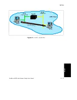
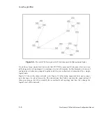
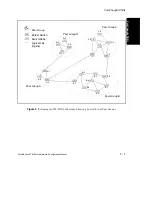
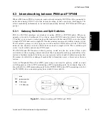
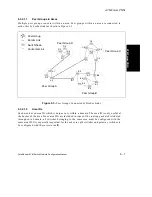
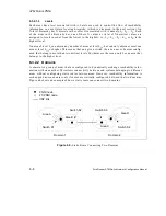
The network shown in Figure 5.3 is organized into four lowest-level peer groups: A, B, C, and
D. The switches within a certain peer group are numbered according to that particular group.
For example, the switches in peer group A are identified as A.1, A.2, and A.3.
Peer groups have a peer group identifier (ID), assigned at configuration time and exchanged
in hello indication messages. Neighboring switches can determine if they belong to the same
peer group by comparing these peer group IDs.
Switches in a peer group are aware of the topology of their own peer group and the existence
of all other peer groups. They recognize the links between their peer group and others, but
they are not aware of internal topology information of other peer groups. Instead, the topolo-
gies of other peer groups are summarized as a single, reachable location, known as a peer
group summary node (PGSN).
5.2.2 Peer Group Topology
To maintain an accurate and updated view of its relative location and status, a switch periodi-
cally sends a hello indication message to every other switch with which it has a direct connec-
tion. These hello indications contain the switch prefix, peer group membership information,
and link metrics (attributes) for the physical link between the two switches.
Through this regular exchange of messages, each switch learns which switches are its immedi-
ate neighbors, to what peer groups they belong, and whether or not the link between itself and
its neighbors is valid.
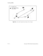
5.2.3 Border Switches
A border switch is any switch that has at least one link to a switch in another peer group. Bor-
der switches play an important role in FT-PNNI because they are responsible for summarizing
reachability information for their respective peer groups, appropriately filtering the flow of
topology database information across peer group boundaries, and building the lowest level
source route for call setups entering the peer group.
Summary of Contents for forerunner series
Page 6: ......
Page 16: ...TOC 10 ForeRunner ATM Switch Network Configuration Manual Table of Contents ...
Page 20: ...LOF 4 ForeRunner ATM Switch Network Configuration Manual List of Figures ...
Page 22: ...LOT 2 ForeRunner ATM Switch Network Configuration Manual List of Tables ...
Page 30: ...viii ForeRunner ATM Switch Network Configuration Manual Preface ...
Page 144: ...3 58 ForeRunner ATM Switch Network Configuration Manual Configuring an Emulated LAN ...
Page 180: ...6 12 ForeRunner ATM Switch Network Configuration Manual ATM Forum PNNI ...
Page 220: ...9 6 ForeRunner ATM Switch Network Configuration Manual Configuring Timing ...
Page 300: ...D 24 ForeRunner ATM Switch Network Configuration Manual Configuring FramePlus Modules ...
Page 308: ...Acronyms 8 ForeRunner ATM Switch Network Configuration Manual Acronyms ...
Page 346: ...Glossary 38 ForeRunner ATM Switch Network Configuration Manual Glossary ...
Page 352: ...Index 6 ForeRunner ATM Switch Network Configuration Manual Index ...


