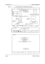
Front Panel and Connectors
Base-520(G) Installation
Page 34
SPARC/CPCI-52x(G)
4.5.4
Serial I/O Interface Connector Pinout
Both serial I/O interfaces of the Base-520(G) are independent full-duplex
channels. For each of them the 4 signals RXD, TXD, RTS, and CTS are
also provided via the respective CompactPCI J5 connector (for interface
A and B see figure 13 “CompactPCI J5 connector pinout” on page 36).
SERIAL A+B on the Base-520(G)’s front panel holds the signals for the
2 serial interfaces A and B.
SERIAL A+B on the Base-520(G)’s front panel holds the signals for the
2 serial interfaces A and B.
Table 17
26-pin serial A+B connector pinout RS232
Signal
Pin
Connector
Pin
Signal
n.c.
1
14
TxD_B (Output)
TxD_A (Output)
2
15
RxC_A (Input)
RxD_A (Input)
3
16
RxD_B (Input)
RTS_A (Output)
4
17
RTxC_A (Input)
CTS_A (Input)
5
18
RxC_B (Input)
DSR_A (Input)
6
19
RTS_B (Output)
GND_A (Ground)
7
20
DTR_A (Output)
DCD_A (Input)
8
21
DSR_B (Input)
n.c.
9
22
RTxC_B (Input)
n.c.
10
23
GND_B (Ground)
DTR_B (Output)
11
24
TxC_A (Output)
DCD_B (Input)
12
25
TxC_B (Output)
CTS_B (Input)
13
26
n.c.
14
1
26
13
Summary of Contents for SPARC/CPCI-520G
Page 6: ...Contents Page iv SPARC CPCI 52x G...
Page 14: ...Using This Manual Page xii SPARC CPCI 52x G...
Page 18: ...Page 4 SPARC CPCI 52x G...
Page 20: ...Introduction Page 6 SPARC CPCI 52x G...
Page 24: ...Ordering Information Introduction Page 10 SPARC CPCI 52x G...
Page 58: ...OpenBoot Firmware Base 520 G Installation Page 44 SPARC CPCI 52x G...
Page 66: ...OpenBoot Firmware Base 520 G Installation Page 52 SPARC CPCI 52x G...
Page 102: ...Ethernet and EBus2 Devices PCIO Hardware Description Page 88 SPARC CPCI 52x G...
Page 114: ...PMC Slots with Busmode Support Hardware Description Page 100 SPARC CPCI 52x G...
Page 134: ......


