Assembly Instructions
Toll free: 1-877-483-6759
IMPORTANT: Please read this manual carefully before beginning assembly of this product. Keep this manual for future reference.
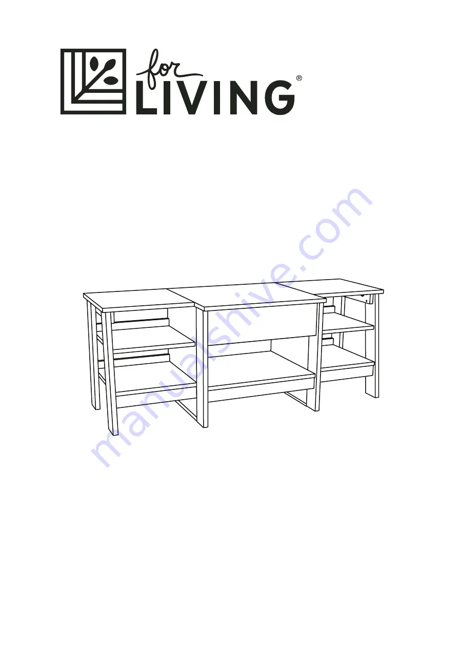
Trestle Entertainment Unit
Product No. 168-0043-0Model No. 424230
Page 1: ...ions Toll free 1 877 483 6759 IMPORTANT Please read this manual carefully before beginning assembly of this product Keep this manual for future reference Trestle Entertainment Unit Product No 168 0043 0 Model No 424230 ...
Page 2: ...comes to products for your home it s essential they stand up to the realities of everyday family life Designed with your family in mind For Living products combine timeless style and family friendly features Now you can focus on what s important creating lasting memories with your family ...
Page 3: ...t is not intended to support a TV NEVER exceed the maximum size and weight of the TV shown in the instructions Be sure to apply the TV warning label as shown in the instructions Overloading drawers and shelves may result in furniture that can break or sag or tip over which may result in injury NEVER exceed the weight limits shown in the instructions Place the heavier items on lower shelves as far ...
Page 4: ...6 6 Left top 1 11 11 Top molding 2 12 12 Molding 4 13 13 Left brace 1 14 14 Long skirt 1 15 15 Left shelf 1 16 16 Centre bottom 1 17 17 Right shelf 1 18 18 Back 1 19 19 Left bottom 1 20 20 Right bottom 1 21 21 Right front leg 1 1 1 Centre top 1 10 10 Right centre leg 1 3 3 Left back leg 1 8 8 Right top 1 9 9 Left front leg 1 7 7 ...
Page 5: ...on this shelf Refer to instruction book for complete safety information Note This is a permanent label Do not try to remove Surface will be damaged 01 18 Ne jamais utiliser ce meuble avec un téléviseur qui soit trop large ou trop lourd Risque de provoquer des blessures graves voire mor telles Le téléviseur et le meuble seront instables et risquent de se renverser Le téléviseur doit peser 22 6 kg o...
Page 6: ...PORTANT Please read and understand this manual before any assembly Before beginning assembly of product make sure all parts are present Compare parts with packaging contents list If any part is missing or if you have any questions contact the service centre at 1 877 483 6759 toll free Place all parts from the box in a cleared area and position them on the floor in front of you Remove all packing m...
Page 7: ... Turn forty three CAM SCREWS G into the exact holes shown in the LEGS 1 2 3 5 7 and 8 UPRIGHTS 4 and 6 TOPS 9 10 and 11 BOTTOMS 17 20 and 21 and DRAWER FRONT 24 G G 9 9 10 10 11 11 21 21 17 17 20 20 6 6 4 4 1 1 8 8 3 3 5 5 7 7 2 2 24 24 G G 43 used Assembly ...
Page 8: ...2 BRACES 14 and 28 SHELVES 16 and 18 and BOTTOMS 17 20 and 21 Push four SMALL HIDDEN CAMS F into the DRAWER SIDES 25 and 26 Product No 168 0043 0 Model No 424230 F F E E 25 25 26 26 F F E E 47 used The arrow in the HIDDEN CAM must point toward the hole in the edge of the board Hole Arrow 22 22 21 21 17 17 20 20 14 14 28 28 18 18 16 16 4 4 6 6 3 3 5 5 12 12 12 12 22 22 15 15 9 9 10 10 11 11 ...
Page 9: ...13 13 13 13 13 13 13 NOTE The larger holes must face out so the SCREWS seat into the holes Shown at actual size L L S u r f a c e w i t h o u t H I D D E N C A M S 16 16 S u r f a c e w i t h o u t H I D D E N C A M S 20 20 S u r f a c e w i t h o u t H I D D E N C A M S 21 21 S u r f a c e w i t h o u t H I D D E N C A M S These surfaces should be even L L 8 used ...
Page 10: ...2 to the BOTTOMS 20 and 21 Tighten four HIDDEN CAMS Product No 168 0043 0 Model No 424230 20 20 S u r f a c e w i t h o u t H I D D E N C A M S 21 21 S u r f a c e w i t h o u t H I D D E N C A M S S u r f a c e w i t h H I D D E N C A M S 22 22 15 15 17 17 22 22 1 2 Surface with HIDDEN CAMS Surface with HIDDEN CAMS Surface with HIDDEN CAMS ...
Page 11: ...RIGHT 6 to the CENTRE BOTTOM 17 and BACK 19 Use four BLACK 1 9 16 FLAT HEAD SCREWS L NOTE Start each SCREW a few turns before completely tightening any of them Shown at actual size L L 15 15 17 17 6 6 Curved edge Surface with CAM SCREWS 19 19 Curved edge L L ...
Page 12: ... CENTRE BOTTOM 17 and BACK 19 Use four BLACK 1 9 16 FLAT HEAD SCREWS L NOTE Start each SCREW a few turns before completely tightening any of them Product No 168 0043 0 Model No 424230 Shown at actual size L L 17 17 4 4 Surface without CAM SCREWS Curved edge 19 19 L L ...
Page 13: ...Step 7 Requires 3 5 Fasten the CENTRE LEGS 3 and 5 to the LONG SKIRT 15 and CENTRE BOTTOM 17 Tighten four HIDDEN CAMS 17 17 15 15 3 3 5 5 The HIDDEN CAM is closer to this edge The HIDDEN CAM is closer to this edge ...
Page 14: ...in a later step Fasten the RIGHT SHELF 18 and RIGHT BOTTOM 21 to the RIGHT UPRIGHT 4 Tighten four HIDDEN CAMS Note The TOP MOLDING 12 is not fastened to the RIGHT UPRIGHT 4 in this step Product No 168 0043 0 Model No 424230 21 21 18 18 4 4 Surface with HIDDEN CAMS 13 13 Surface without HIDDEN CAMS 12 12 Unfinished edge Finished edge ...
Page 15: ... and 2 to the RIGHT SHELF 18 and RIGHT BOTTOM 21 Tighten four HIDDEN CAMS NOTE You will need to use your Short Screwdriver for the RIGHT SHELF 18 21 21 18 18 28 28 2 2 1 1 12 12 Note The RIGHT BACK LEG 2 is not fastened to the TOP MOLDING 12 in this step 28 28 2 2 1 1 Surface with HIDDEN CAMS Unfinished edge Shown at actual size M M M M M M ...
Page 16: ...tened in a later step Fasten the LEFT SHELF 16 and LEFT BOTTOM 20 to the LEFT UPRIGHT 6 Tighten four HIDDEN CAMS Product No 168 0043 0 Model No 424230 Note The TOP MOLDING 12 is not fastened to the LEFT UPRIGHT 6 in this step 20 20 16 16 6 6 12 12 Surface with HIDDEN CAMS Surface without HIDDEN CAMS Unfinished edge Finished edge ...
Page 17: ... 7 and 8 to the LEFT SHELF 16 and LEFT BOTTOM 20 Tighten four HIDDEN CAMS NOTE You will need to use your Short Screwdriver for the LEFT SHELF 16 Note The LEFT BACK LEG 8 is not fastened to the TOP MOLDING 12 in this step 20 20 16 16 14 14 7 7 8 8 14 14 7 7 8 8 12 12 Surface with HIDDEN CAMS Unfinished edge Shown at actual size M M M M M M ...
Page 18: ...AD SCREWS N Fasten the CABINET LEFT B to the LEFT CENTRE LEG 5 and LEFT UPRIGHT 6 Use three SILVER 3 8 FLAT HEAD SCREWS N Note Use the 2nd 6th and 12th holes from the roller end of the rail Product No 168 0043 0 Model No 424230 4 4 3 3 5 5 6 6 A A Roller end 2nd hole 12th hole 6th hole B B N N 6 used Roller end Shown at actual size N N ...
Page 19: ...OPS 9 and 11 Use four DOUBLE DOWELS H and tighten eight HIDDEN CAMS Fasten the TOPS 9 10 and 11 to the LEGS 3 and 5 UPRGHTS 4 and 6 and BRACES 14 and 28 Tighten ten HIDDEN CAMS 11 11 9 9 10 10 11 11 10 10 9 9 H H 14 14 5 5 6 6 4 4 3 3 These edges must be even 28 28 H H H H ...
Page 20: ...hem Slide the DRAWER BOTTOM 23 into the grooves in the DRAWER SIDES 25 and 26 and DRAWER BACK 27 Fasten the DRAWER FRONT 24 to the DRAWER SIDES 25 and 26 Tighten four HIDDEN CAMS Product No 168 0043 0 Model No 424230 Shown at actual size L L Groove 27 27 26 26 25 25 27 27 26 26 25 25 23 23 26 26 25 25 23 23 24 24 Be sure the DRAWER BOTTOM inserts into the DRAWER FRONT groove F i n i s h e d s u r ...
Page 21: ... DRAWER RIGHT C to the RIGHT DRAWER SDIE 26 Use two SILVER 3 8 FLAT HEAD SCREWS N Fasten the DRAWER LEFT D to the LEFT DRAWER SDIE 25 Use two SILVER 3 8 FLAT HEAD SCREWS N 26 26 25 25 Roller end D D C C Roller end N N N N Shown at actual size N N ...
Page 22: ...ble and may tip The TV must weigh less than 50 lbs The base of the TV must be able to sit completely on this shelf Refer to instruction book for complete safety information Note This is a permanent label Do not try to remove Surface will be damaged 01 18 Ne jamais utiliser ce meuble avec un téléviseur qui soit trop large ou trop lourd Risque de provoquer des blessures graves voire mor telles Le té...
Page 23: ...domestic indoor use only The product should be placed on a flat horizontal surface Arrange necessary manpower when assembling or moving the product Do not push furniture especially on a carpeted floor Have someone help you lift heavy items and set it in place Cleaning and Maintenance Technical Data Dimensions W x D x H 126 x 47 x 49 3 cm 49 5 8 x18 1 2 x 19 3 8 Product weight 26 8 kg 59 lb 23 ...
Page 24: ...in workmanship and materials Trileaf Distribution agrees to replace the defective product free of charge within the stated warranty period when returned by the original purchaser with proof of purchase This product is not guaranteed against wear or breakage due to misuse and or abuse ...
Page 25: ...s 1 877 483 6759 IMPORTANT Veuillez lire attentivement le présent guide avant de commencer l assemblage de cet article Conservez ce guide à titre de référence Unité de divertissement à tétreaux No d article 168 0043 0 No de modèle 424230 ...
Page 26: ...yer il est essentiel qu ils soient à la hauteur des réalités de la vie familiale Conçus pour votre famille les articles For LivingMD combinent un style intem porel et des caractéristiques fonctionnelles pour la famille Vous pouvez donc vous concentrer sur ce qui importe vraiment et vivre des moments inoubliables en famille ...
Page 27: ...taille et de poids du téléviseur figurant dans les instructions Assurez vous d appliquer l étiquette d avertissement comme indiqué dans les instructions Des tiroirs et tablettes surchargées peuvent briser le meuble causer un affaissement ou le faire tomber ce qui peut entraîner des blessures Ne dépassez JAMAIS les limites de poids indiquées dans les instructions Placez les articles les plus lourds ...
Page 28: ...périeure 2 13 13 Moulure 4 14 14 Renfort gauche 1 15 15 Barre longue 1 16 16 Tablette gauche 1 17 17 Panneau inférieur central 1 18 18 Tablette droite 1 19 19 Panneau arrière 1 20 20 Panneau inférieur gauche 1 21 21 Panneau inférieur droit 1 1 1 Pied avant droit 1 10 10 Surface supérieure centrale 1 Pied central droit 1 3 3 8 8 Pied arrière gauche 1 Surface supérieure droite 1 9 9 7 7 Pied avant g...
Page 29: ... able to sit completely on this shelf Refer to instruction book for complete safety information Note This is a permanent label Do not try to remove Surface will be damaged 01 18 Ne jamais utiliser ce meuble avec un téléviseur qui soit trop large ou trop lourd Risque de provoquer des blessures graves voire mor telles Le téléviseur et le meuble seront instables et risquent de se renverser Le télévis...
Page 30: ...uer avec nous nous sommes là pour vous aider IMPORTANT Veuillez lire ce guide et bien le comprendre avant de commencer l assemblage Assurez vous que toutes les pièces sont présentes avant de commencer l assemblage Comparez les pièces avec la liste du contenu de l emballage S il manque une pièce ou si vous avez des questions composez le numéro sans frais 1 877 483 6759 Placez toutes les pièces de l...
Page 31: ...IS DE CAME G dans les trous exacts illustrés dans les PIEDS 1 2 3 5 7 et 8 MONTANTS 4 et 6 SURFACES SUPÉRIEURES 9 10 et 11 PANNEAUX INFÉRIEURS 17 20 et 21 et dans l AVANT DU TIROIR 24 G G 9 9 10 10 11 11 21 21 17 17 20 20 6 6 4 4 1 1 8 8 3 3 5 5 7 7 2 2 24 24 G G 43 utilisées Assemblage ...
Page 32: ...S 14 et 28 TABLETTES 16 et 18 et PANNEAUX INFÉRIEURS 17 20 et 21 Insérez 4 PETITES VIS DE CAME DISSIMULÉES F dans les CÔTÉS DU TIROIR 25 et 26 No d article 168 0043 0 No de modèle 424230 F F E E 25 25 26 26 F F E E 47 utilisées 22 22 21 21 17 17 20 20 14 14 28 28 18 18 16 16 4 4 6 6 3 3 5 5 12 12 12 12 22 22 15 15 9 9 10 10 11 11 La flèche dans la VIS DE CAME DISSIMULÉE doit pointer vers le trou da...
Page 33: ...E Les plus grands trous doivent pointer vers l extérieur pour que les VIS se fixent dans les trous Taille réelle L L S u r f a c e s a n s V I S D E C A M E D I S S I M U L É E S 16 16 S u r f a c e s a n s V I S D E C A M E D I S S I M U L É E S 20 20 S u r f a c e s a n s V I S D E C A M E D I S S I M U L É E S 21 21 S u r f a c e s a n s V I S D E C A M E D I S S I M U L É E S Ces surfaces doive...
Page 34: ...1 Serrez 4 VIS DE CAME DISSIMULÉES No d article 168 0043 0 No de modèle 424230 20 20 S u r f a c e s a n s V I S D E C A M E D I S S I M U L É E S 21 21 S u r f a c e s a n s V I S D E C A M E D I S S I M U L É E S S u r f a c e a v e c V I S D E C A M E D I S S I M U L É E S 22 22 15 15 17 17 22 22 1 2 Surface avec VIS DE CAME DISSIMULÉES Surface avec VIS DE CAME DISSIMULÉES Surface avec VIS DE C...
Page 35: ...GAUCHE 6 au PANNEAU INFÉRIEUR CENTRAL 17 et au PANNEAU ARRIÈRE 19 Utilisez 4 VIS À TÊTE PLATE NOIRES 1 9 16 PO L REMARQUE Tournez chaque VIS légèrement avant d en serrer une au complet Taille réelle L L 15 15 17 17 6 6 Bord courbé Surface avecVIS DE CAME 19 19 Bord courbé L L ...
Page 36: ...ÉRIEUR CENTRAL 17 et au PANNEAU ARRIÈRE 19 Utilisez 4 VIS À TÊTE PLATE NOIRES 1 9 16 PO L REMARQUE Tournez chaque VIS légèrement avant d en serrer une au complet No d article 168 0043 0 No de modèle 424230 Taille réelle L L 17 17 4 4 Surface sans VIS DE CAME DISSIMULÉES Bord courbé 19 19 L L ...
Page 37: ...5 Vissez les PIEDS DU CENTRE 3 et 5 à la BARRE LONGUE 15 et au PANNEAU INFÉRIEUR CENTRAL 17 Serrez 4 VIS DE CAME DISSIMULÉES 17 17 15 15 3 3 5 5 La VIS DE CAME DISSIMULÉE est plus proche de ce côté La VIS DE CAME DISSIMULÉE est plus proche de ce côté ...
Page 38: ...rieure Vissez la TABLETTE DROITE 18 et le PANNEAU INFÉRIEUR DROIT 21 au MONTANT DROIT 4 Serrez 4 VIS DE CAME DISSIMULÉES Remarque La MOULURE SUPÉRIEURE 12 n est pas vissée au MONTANT DROIT 4 dans cette étape No d article 168 0043 0 No de modèle 424230 21 21 18 18 4 4 13 13 Surface sans VIS DE CAME DISSIMULÉES 12 12 Bord non fini Bord fini Surface avec VIS DE CAME DISSIMULÉES ...
Page 39: ...ABLETTE DROITE 18 et au PANNEAU INFÉRIEUR DROIT 21 Serrez 4 VIS DE CAME DISSIMULÉES REMARQUE Vous devrez utiliser votre tournevis court pour la TABLETTE DROITE 18 21 21 18 18 28 28 2 2 1 1 12 12 Remarque Le PIED ARRIÈRE DROIT 2 n est pas vissé à la MOULURE SUPÉRIEURE 12 dans cette étape 28 28 2 2 1 1 Surface avec VIS DE CAME DISSIMULÉES Bord non fini Taille réelle M M M M M M ...
Page 40: ...ltérieure Vissez la TABLETTE GAUCHE 16 et le PANNEAU INFÉRIEUR GAUCHE 20 au MONTANT GAUCHE 6 Serrez 4 VIS DE CAME DISSIMULÉES No d article 168 0043 0 No de modèle 424230 Remarque La MOULURE SUPÉRIEURE 12 n est pas vissée au MONTANT GAUCHE 6 dans cette étape 20 20 16 16 6 6 12 12 Surface sans VIS DE CAME DISSIMULÉES Bord non fini Bord fini Surface avec VIS DE CAME DISSIMULÉES ...
Page 41: ...ABLETTE GAUCHE 16 et au PANNEAU INFÉRIEUR GAUCHE 20 Serrez 4 VIS DE CAME DISSIMULÉES REMARQUE Vous devrez utiliser votre tournevis court pour la TABLETTE GAUCHE 16 Remarque Le PIED ARRIÈRE GAUCHE 8 n est pas vissé à la MOULURE SUPÉRIEURE 12 dans cette étape 20 20 16 16 14 14 7 7 8 8 14 14 7 7 8 8 12 12 Taille réelle M M M M M M Surface avec VIS DE CAME DISSIMULÉES Bord non fini ...
Page 42: ...sez le RAIL GAUCHE B à la PATTE CENTRALE GAUCHE 5 et au MONTANT GAUCHE 6 Utilisez 3 VIS À TÊTE PLATE ARGENTÉES 3 8 PO N Remarque Utilisez les 2e 6e et 12e trous à partir du butoir de roulettes sur le rail No d article 168 0043 0 No de modèle 424230 4 4 3 3 5 5 6 6 A A Butoir des roulettes 2e trou 12e trou 6e trou B B N N 6 utilisées Butoir des roulettes Taille réelle N N ...
Page 43: ...PÉRIEURES 9 et 11 Utilisez 4 GOUJONS DOUBLES H et vissez 8 VIS DE CAME DISSIMULÉES Vissez les SURFACES SUPÉRIEURES 9 10 et 11 aux PIEDS 3 et 5 aux MONTANTS 4 et 6 et aux RENFORTS 14 et 28 Serrez 10 VIS DE CAME DISSIMULÉES 11 11 9 9 10 10 11 11 10 10 9 9 H H 14 14 5 5 6 6 4 4 3 3 Ces bords doivent être égaux 28 28 H H H H ...
Page 44: ...z le BAS DU TIROIR 23 dans les rainures situées dans les CÔTÉS DU TIROIR 25 et 26 et l ARRIÈRE DU TIROIR 27 Vissez le DEVANT DU TIROIR 24 aux CÔTÉS DU TIROIR 25 et 26 Serrez 4 VIS DE CAME DISSIMULÉES No d article 168 0043 0 No de modèle 424230 Taille réelle L L Rainure 27 27 26 26 25 25 27 27 26 26 25 25 23 23 26 26 25 25 23 23 24 24 Assurez vous que le BAS DU TIROIR est bien inséré dans la rainur...
Page 45: ...R DROIT C au CÔTÉ DROIT DU TIROIR 26 Utilisez 2 VIS À TÊTE PLATE ARGENTÉES 3 8 PO N Vissez le TIROIR GAUCHE D au CÔTÉ GAUCHE DU TIROIR 25 Utilisez 2 VIS À TÊTE PLATE ARGENTÉES 3 8 PO N 26 26 25 25 D D C C N N N N Taille réelle N N Butoir de roulettes Butoir de roulettes ...
Page 46: ...r use this furniture with a TV that is too large or too heavy Severe injury or death can occur The TV and furniture will be unstable and may tip The TV must weigh less than 50 lbs The base of the TV must be able to sit completely on this shelf Refer to instruction book for complete safety information Note This is a permanent label Do not try to remove Surface will be damaged 01 18 Ne jamais utilis...
Page 47: ...dentiel à l intérieur Cet article doit être placé sur un sol plat Prévoyez la main d œuvre nécessaire pour assembler ou déplacer l article Ne poussez pas les meubles surtout sur un plancher recouvert de tapis Demandez à quelqu un de vous aider pour déplacer et fixer vos articles lourds Nettoyage et entretien Caractéristiques techniques Dimensions la x P x H 126 x 47 x 49 3 cm 49 5 8 x 18 1 2 x 19 3...
Page 48: ...x et de fabrication Distribution Trifeuil consent à remplacer l article défectueux sans frais lorsqu il est retourné accompagné de la preuve d achat par l acquéreur initial au cours de la période de garantie convenue Cet article n est pas garanti contre l usure ou un bris causé par un usage abusif ou inapproprié ...