8
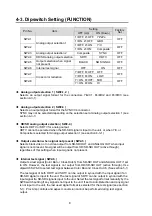
4-3. Dipswitch Setting (FUNCTION)
Setting
Pin No.
Item
OFF (Up)
ON (Down)
Factory
Set
1=OFF, 2=OFF: YP
B
P
R
SW2-1
1=ON, 2=OFF:
GBR
OFF
1=OFF, 2=ON:
Y/C
SW2-2
Analog output selection 1
1=ON, 2=ON:
Composite
OFF
SW2-3
Analog output selection 2
Composite
SYNC
OFF
SW2-4
HD/SD analog output selection
SDTV
HDTV
OFF
SW2-5
Output selection when signal
not present
BLACK NO
SIGNAL OFF
SW2-6 Internal
test
signal
OFF
ON
OFF
7=OFF, 8=OFF: OFF
SW2-7
7=OFF, 8=ON:
LOW
OFF
7= ON, 8=OFF: MID
SW2-8
Cross color reduction
7= ON, 8=ON:
HI
OFF
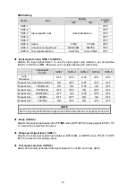
Analog output selection 1 ( SW2-1, 2 )
Selects an output signal format for the connectors Y/G/C1, P
B
/B/C2 and P
R
/R/C3 (see
Analog output selection 2 ( SW2-3 )
Selects an output signal format for the SYNC/C4 connector.
SYNC may not be selected depending on the selection set at Analog output selection 1 (see
section 4-3-1).
HD/SD analog output selection ( SW2-4 )
Selects HDTV or SDTV for analog output.
HDTV cannot be selected when the SD-SDI signal is input to the unit, or when Y/C or
Composite is selected for Analog output selection 1 (see section 4-3-1).
Output selection when signal not present ( SW2-5 )
Selects black video or no video output from SD-SDI OUT and ANALOG OUT when input
signal is not present. No signal will be output from HD/SD-SDI OUT (active through)
regardless of this setting when input signal is not present.
Internal test signal ( SW2-6 )
Outputs a test signal (Color Bar or Cross Hatch) from SD-SDI OUT and ANALOG OUT if set
to ON. However, the test signal is not output from HD/SD-SDI OUT (active through). Use
dipswitch SW6-8 to select test signal between Color Bar and Cross Hatch. (See section 5-1)
The test signal of both HDTV and SDTV can be output in synced with the input signal if an
HD-SDI signal is input to the unit. The test signal of SDTV can be output in synced with the
input signal if a SD-SDI signal is input to the unit. Select the test signal format manually by the
SW6 switch setting if any signal is not input to the unit. If set to Auto Detection and any signal
is not input to the unit, the last used signal format is selected for the test signal (see section
5-1). Proc Amp controls and aspect conversion cannot be performed during test signal
output.
Summary of Contents for UFH-70DCM
Page 1: ...UFH 70DCM HD SD Down Converter with D A Converter 1st Edition Rev 1 OPERATION MANUAL...
Page 2: ......
Page 6: ......
Page 22: ......

